Bicycle digital spoke tension meter based on Jobst Brandt design
prusaprinters
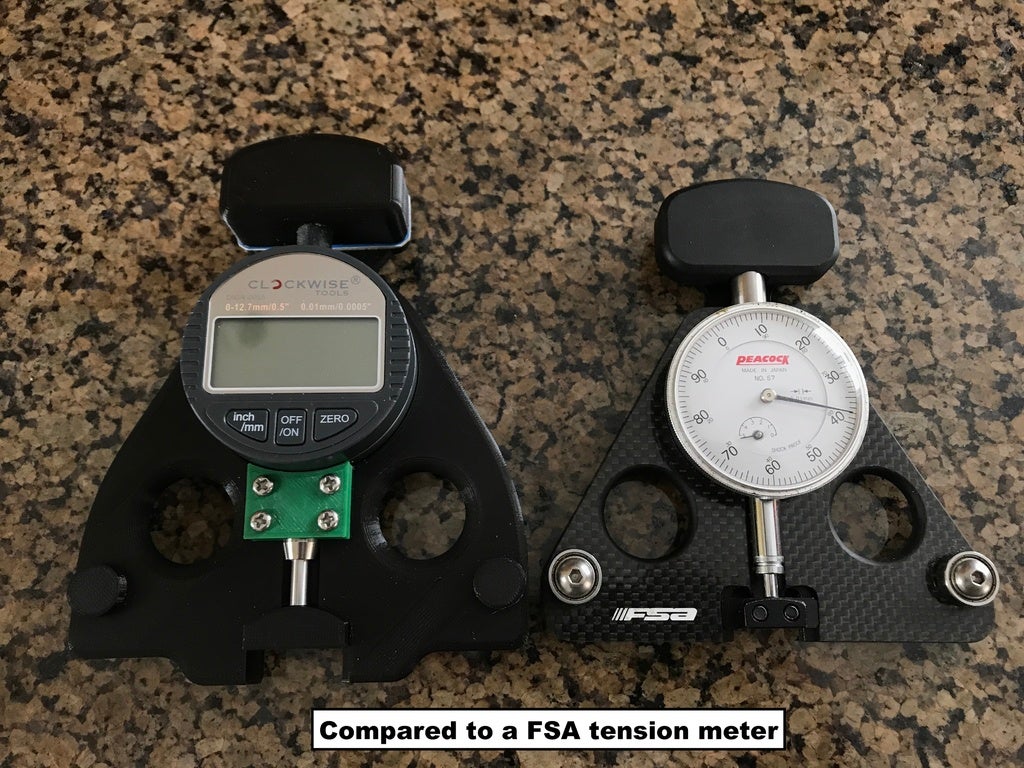
<p><strong>Note:*</strong>This is<strong>very much</strong> still a work in progress, and I still have work to do, so if you'd like updates, make sure to click the "Watch" button. Just clicking like or adding it to a collection won't get you those updates.*</p> <p>This is a spoke tension meter which uses a spring to create a deflection in a bicycle spoke and a digital gauge to read the deflection. This deflection corresponds to the tension in the spoke. Knowing the tension allows a wheel builder to build to the recommended maximum tension dictated by the rim, and also allows the spoke tension to be balanced, avoiding excessively tight or excessively loose spokes.</p> <p>This design is based heavily on the original Jobst Brandt design which dates back to 1975. While there are other spoke tension meters out there, I like the Brandt design as it uses a fairly light spring to not add too much deflection to the spoke, and it measures on the same side as the reference points, so is less affected by spoke geometry.</p> <p>Huge credit goes to <a href="/Modellaner">Modellaner</a> for his <a href="https://www.thingiverse.com/thing:2810089">Tensiometer</a> which got me started on this whole thing. It's been such a fun project and I'm nowhere near done yet. Big thanks also go to <a href="/QuangVuong/about">Quang Vuong</a> who had the idea long before we did and shared everything he had with us. Thanks also to Modellaner for converting the DXF drawings from Quang Vuong to PDF as my efforts in that weren't going so well. I've included that PDF for reference.</p> <p>This was designed in Fusion 360. In lieu of including the F3D files, which would be static, you can use this link to view the latest version of the design: <a href="https://a360.co/2PcaNK6">https://a360.co/2PcaNK6</a></p> <p><strong>Note:</strong> If you use the gauge I specify, I suggest removing the ball point at the end of the indicator. This doesn't serve any purpose and might make getting a good reading harder as a ball against the side of a cylinder won't be very stable. Plus, it makes the indicator longer and might not give you enough room to insert a spoke when you open the tool. So, before you install the gauge in the tool body, remove the ball point indicator end. This may take some doing as it was installed quite tight on mine. Just use a pair of pliers and unthread it as you would any right-hand screw. You can leave the end of the indicator shaft as it is without anything threaded into the end, the flat end will work nicely with the side of a spoke.</p> <p><strong>Note on other gauges:</strong> Yes, you can swap in any other gauge that fits, but this design is based on certain key dimensions of the gauge that I listed. Another gauge will likely have a different length for the clamp area, and also have a different overall length. None of these things are standardized on linear indicator gauges, and changing any of them changes the function of the tool, so it probably won't work as well for you.</p> <p><strong>Note on lack of bearings:</strong> The idea of this design was to have as few parts that needed to be purchased as possible. To that end, I decided to use smooth posts instead of sealed bearings as are found in the Brandt drawings and on the FSA tensionmeter. Once I have a calibration rig set up, I plan on testing this design against a design with bearings to see if there is a difference in accuracy. Smooth PLA is pretty low friction to begin with, so I'm not expecting a problem.</p> <h3>Print instructions</h3><h3>Category: Hand Tools Summary</h3> <p><strong>Note:*</strong>This is<strong>very much</strong> still a work in progress, and I still have work to do, so if you'd like updates, make sure to click the "Watch" button. Just clicking like or adding it to a collection won't get you those updates.*</p> <p>This is a spoke tension meter which uses a spring to create a deflection in a bicycle spoke and a digital gauge to read the deflection. This deflection corresponds to the tension in the spoke. Knowing the tension allows a wheel builder to build to the recommended maximum tension dictated by the rim, and also allows the spoke tension to be balanced, avoiding excessively tight or excessively loose spokes.</p> <p>This design is based heavily on the original Jobst Brandt design which dates back to 1975. While there are other spoke tension meters out there, I like the Brandt design as it uses a fairly light spring to not add too much deflection to the spoke, and it measures on the same side as the reference points, so is less affected by spoke geometry.</p> <p>Huge credit goes to <a href="/Modellaner">Modellaner</a> for his <a href="https://www.thingiverse.com/thing:2810089">Tensiometer</a> which got me started on this whole thing. It's been such a fun project and I'm nowhere near done yet. Big thanks also go to <a href="/QuangVuong/about">Quang Vuong</a> who had the idea long before we did and shared everything he had with us. Thanks also to Modellaner for converting the DXF drawings from Quang Vuong to PDF as my efforts in that weren't going so well. I've included that PDF for reference.</p> <p>This was designed in Fusion 360. In lieu of including the F3D files, which would be static, you can use this link to view the latest version of the design: <a href="https://a360.co/2PcaNK6">https://a360.co/2PcaNK6</a></p> <p><strong>Note:</strong> If you use the gauge I specify, I suggest removing the ball point at the end of the indicator. This doesn't serve any purpose and might make getting a good reading harder as a ball against the side of a cylinder won't be very stable. Plus, it makes the indicator longer and might not give you enough room to insert a spoke when you open the tool. So, before you install the gauge in the tool body, remove the ball point indicator end. This may take some doing as it was installed quite tight on mine. Just use a pair of pliers and unthread it as you would any right-hand screw. You can leave the end of the indicator shaft as it is without anything threaded into the end, the flat end will work nicely with the side of a spoke.</p> <p><strong>Note on other gauges:</strong> Yes, you can swap in any other gauge that fits, but this design is based on certain key dimensions of the gauge that I listed. Another gauge will likely have a different length for the clamp area, and also have a different overall length. None of these things are standardized on linear indicator gauges, and changing any of them changes the function of the tool, so it probably won't work as well for you.</p> <p><strong>Note on lack of bearings:</strong> The idea of this design was to have as few parts that needed to be purchased as possible. To that end, I decided to use smooth posts instead of sealed bearings as are found in the Brandt drawings and on the FSA tensionmeter. Once I have a calibration rig set up, I plan on testing this design against a design with bearings to see if there is a difference in accuracy. Smooth PLA is pretty low friction to begin with, so I'm not expecting a problem.</p> <h3> Print Settings</h3> <p><strong>Printer Brand:</strong> Prusa</p> <p><strong>Printer:</strong> i3 MK3</p> <p><strong>Rafts:</strong> No</p> <p><strong>Supports:</strong> No</p> <p><strong>Resolution:</strong> Various</p> <p><strong>Infill:</strong> various</p> <p><strong>Filament:</strong> AIO Robotics PLA black<br/> <strong>Notes:</strong></p> <p>I used different settings for the different parts. All were sliced in PrusaControl</p> <ul> <li>Main body - 0.15mm layer height, 20% infill, two shells</li> <li>Handle - 0.15mm layer height, 20% infill, two shells</li> <li>Gauge clamp - 0.15mm layer height, 70% infill, two shells</li> <li>Bar with anvil - 0.15mm layer height, 50% infill, two shells</li> <li><p>Spring seat - 0.05mm layer height, 50% infill, two shells<br/> The 0.05mm layer height on the spring seat wasn't absolutely necessary, I was just trying to get better results on the fine M8x0.5mm thread. Considering the M3 threads printed into the main body and handle are the same 0.5mm pitch and printed just fine at the higher 0.15mm layer height, I don't see why this wouldn't work for the spring seat - I just haven't tried it yet.</p> <p>I've also carefully designed all the parts so that they don't need any supports when printed as-is. You may choose to add them, but if your printer is pretty well calibrated and you use the settings I list above, you should be able to print with no supports and still get really good results.</p> <p>I also have a Monoprice Select Mini printer with a 120mm build volume - and I have managed to keep all of the parts<em>just</em> inside that volume. The bar with anvil needs to be rotated 45 degrees, and you'll have to turn off any skirt, brim, or raft, but it<em>just</em> fits.</p> <h3>Design details</h3> </li> </ul> <p><strong>Design history</strong></p> <p>...need more info here.</p> <p>Original design: Jobst Brandt, 5 November 1975<br/> First 3D printed version: <a href="/QuangVuong/about">Quang Vuong</a><br/> Another <a href="https://www.thingiverse.com/thing:2810089">3D printed version</a>: <a href="/Modellaner">Modellaner</a></p> <p><a href="https://www.thingiverse.com/thing:3209607">3D printed version of the DT Swiss tension meter</a> by <a href="/WheresWaldo">WheresWaldo</a></p> <p><a href="https://www.thingiverse.com/thing:2810089/comments">Original comment thread</a> on the Modellaner design.<br/> <a href="/groups/bike/forums/general/topic:28979">Follow-up discussion</a> on the <a href="/groups/bike">Bike group</a></p> <p><strong>Required hardware</strong></p> <p>I designed this to need as few non-printable parts as possible. I've got the list down to only three different types of parts:</p> <p>1.<strong>12.7mm digital indicator</strong><br/> I found <a href="http://a.co/d/eSaJKBw">this version from Clockwise Tools on Amazon</a> but this looks to be a generally available gauge from many vendors.<br/> 3.<strong>M3x16mm screws</strong><br/> A total of 8 are needed, but a <a href="http://a.co/d/87aTcTv">pack of them</a> is cheap enough. Alternatively, you can find these at most hardware stores. You may wish to add M3 washers, but it's not absolutely necessary.<br/> 5.<strong>A Lee LC-032E-15 spring</strong><br/> which has the following specifications:</p> <pre><code>* 0.36" OD * 0.032" wire diameter (music wire, not stainless) * 2" free length * 4 lbs/in spring rate I found [this one on Amazon](http://a.co/d/3mUUVHh) but it's currently unavailable. </code></pre> <p>I've created <a href="http://a.co/bjX81eE">this list on Amazon</a> with these parts.</p> <h3> Using the tension meter</h3> <p><strong>Assembly</strong></p> <p>Detail how to put the parts together</p> <p><strong>Usage</strong></p> <p>Detail how to actually use it. (include the spreadsheet?)</p>
With this file you will be able to print Bicycle digital spoke tension meter based on Jobst Brandt design with your 3D printer. Click on the button and save the file on your computer to work, edit or customize your design. You can also find more 3D designs for printers on Bicycle digital spoke tension meter based on Jobst Brandt design.