Binary Clock
thingiverse
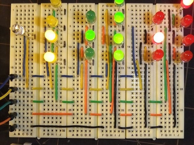
First updates on Dec 16, 2013 included BLINK_TEST, a debugging feature that blinks all lights sequentially to check wiring accuracy. Each light should activate for one second before the next follows suit in sequence. This is helpful as any misfired or out-of-place lit LED indicates a wiring issue. An early May 2012 update featured a Fritzing file illustrating Binary Clock's schematic. The file can be downloaded from Fritzing.org. However, the creator admitted that the PCB and schematic views might need improvement. If you're interested in contributing to its upgrade, feel free to reach out. The author started his Arduino journey with a UNO starter kit, choosing to create a binary clock as his initial project. LED colors represent Am (white), current hour (yellow), minutes (green), and seconds (red). Familiarity with binary is helpful but an introduction can be found on Wikipedia. A video of the functioning clock is available on YouTube. This project remains work-in-progress as a 3D printable case design for the clock is in the pipeline. The Arduino source code is provided, assuming basic programming knowledge on Arduino boards. Charlieplexing technique is used to handle all 19 timer lights using just five digital pins. Color-coded pin wires (8=Black, 9=Orange, 10=Green, 11=Yellow, 12=Blue) are connected to LEDs as depicted in the pictures. Each LED is oriented with cathode then anode, requiring proper plug-in for functionality. Three buttons (Hour, Minute, and Second Reset) on pins 2, 3, and 4 allow time setting by incrementing hours or minutes or resetting seconds. An LED also lights up upon button press to indicate action. The creator plans to design a 3D printable case for the assembly in the near future.
With this file you will be able to print Binary Clock with your 3D printer. Click on the button and save the file on your computer to work, edit or customize your design. You can also find more 3D designs for printers on Binary Clock.