Binary Clock Pico W individual LEDs
thingiverse
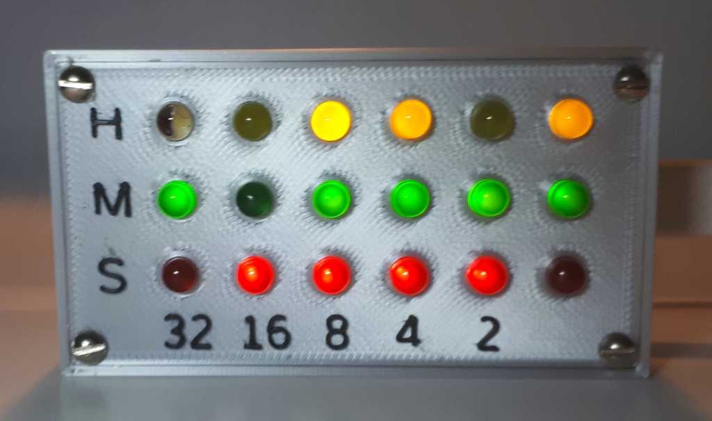
** A binary clock ** project based on Hackspace magazine ideas, but with internet time and daylight time shifts. This binary clock uses individual LEDs, driven by a Raspberry Pico W micro-controller. Here's a short video of the clock starting: https://www.youtube.com/watch?v=ZOUNjKuRbA0 I saw an item in Hackspace Magazine #63 pages 54 – 57, showing a basic binary clock getting its time from the internet. That caught my attention. (Download the magazine for free (or you might think they're worth giving a donation to - I do): https://hackspace.raspberrypi.com/issues/63/pdf) I thought I’d start with that and add some more features. I’ve put on Github my Python code that drives the basic clock, but also re-syncs with the internet daily and picks up Summer/Winter time changes. https://github.com/viragored/Binary-LEDs-clock In the files I’ve uploaded here is the OpenSCAD source. It’s as parametric as I could make it, and hopefully fairly self-explanatory. The .stl files are all generated from that file – their file names should make clear what model is in each file. Settings you can choose in OpenSCAD are the size of the LEDs (3mm or 5mm), the size of the clearance holes for the screws in the lid, and the diameter of the thread hole in the box corners. # Making the clock # You’ll need to print the box and a lid to go with it. ** The lid: ** The LEDs I had were nominally 5mm, but some were smaller than that size. I printed the holes to fit the smallest ones, then filed the other holes so all the LEDs fitted in to about the same depth. There is a test file called “testsquare.stl” to print a set of three holes to try your LEDs in. The middle hole in that file is 4.8mm (which I printed mine at), and there is one hole at 4.7 and another at 4.9. ** Wiring: ** To wire up the model, I found this method easier than the way that Hackspace suggested. - Superglue the LEDs in place, orienting carefully to allow the Ground legs to bend and not touch the Positive legs - Solder all the Negative/Ground legs together, leaving one long to receive cable from the Pico - Trim the Positive legs to suitable length - Trim the wires on the resistors to suitable length - Solder connecting cable to resistor - Solder resistor to LED Positive leg - Slide heat-shrink over the resistor and bare wire and shrink - Solder cable to Pico When my soldering was complete, I tested that all the LEDs were working. There’s a Python script on Github to do that. https://github.com/viragored/Binary-LEDs-clock Only then was I ready to put the electronics into the box. I think it's worth experimenting with different resistor values for the LEDs. Each colour shines at a different brightness with the same resistor. I used 2k for Yellow, 510 for Green, 5k for Red and 10k for white to get a similar amount of shine from each. ** The box: ** To make sure that the Pico would snap tightly into the base of the box, I printed a small section of the box. (PrusaSlicer allows cutting out a section of a model.) My Pico and the filament I used make a very tight fit so I’ve not glued the Pico in. Snap or glue the Pico in, push the wires into the box carefully, and get the lid down to its proper position – and check the LEDs again! (A couple of my solder joints had come apart as I was pushing the electronics into the box.) When you're satisfied, fasten the lid onto the box - then you’re ready to go!
With this file you will be able to print Binary Clock Pico W individual LEDs with your 3D printer. Click on the button and save the file on your computer to work, edit or customize your design. You can also find more 3D designs for printers on Binary Clock Pico W individual LEDs.