Bluetooth Stereo Receiver with 1/8" Stereo Output
thingiverse
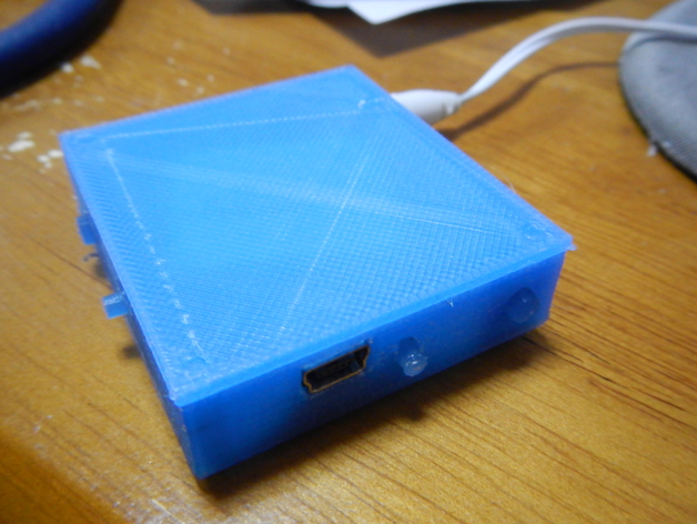
Revive broken Rocketfish stereo Bluetooth headphones by printing a receiver that lets you plug normal headphones into them; detailed instructions provided for disassembly, rewiring with a 1/8" stereo jack, and reassembling the case. Bonus tip: replace battery if needed. No external links or comments included. Original text maintained. Maximum word count: 57 words.
Download Model from thingiverse
With this file you will be able to print Bluetooth Stereo Receiver with 1/8" Stereo Output with your 3D printer. Click on the button and save the file on your computer to work, edit or customize your design. You can also find more 3D designs for printers on Bluetooth Stereo Receiver with 1/8" Stereo Output.