Box-e RGB LED Desk Lamp
thingiverse
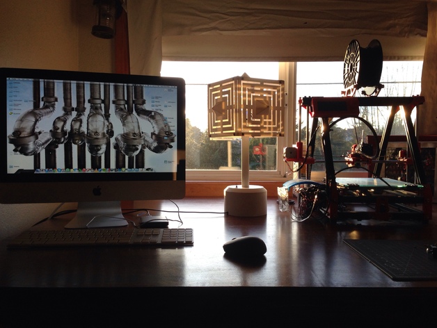
A sleek lamp to illuminate your workspace comes alive with vibrant color, cast cool shadows, and showcases your desktop manufacturing prowess. With two customizable RGB LEDs fueled by an Arduino board, you're free to control lighting to suit your every whim. Assemble, solder, and program - all is made simple by the provided sample code. This lamp excels at: Casting intriguing shadows Guiding beginners through the Arduino environment Demonstrating DIY prowess Perfectly illuminating specific shades of blue Unfortunately, this masterpiece does falter in its inability to provide functional light. Indulge in the thrill of watching it come alive! Future updates include seamless color fades, button-based sequences, and customizable lighting schedules - all contingent on community interest. Once there's sufficient demand, complete project files will be shared, ensuring anyone can bring this vision to life.
With this file you will be able to print Box-e RGB LED Desk Lamp with your 3D printer. Click on the button and save the file on your computer to work, edit or customize your design. You can also find more 3D designs for printers on Box-e RGB LED Desk Lamp.