BU0836A controller board holder for Saitek's Pro Flight Yoke
thingiverse
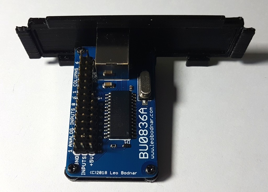
This mod is the follow-up for the 180 degree rotation mod that was applied to the Saitek Pro Flight Yoke. More info about the earlier mod can be found here: https://www.thingiverse.com/thing:4596632 This is the holder for the Leo Bodnar's BU0836A controller board. It allows to install the board into the Saitek's Pro Flight Yoke instead of the original board (in case it's broken). The yoke's roll and pitch movements become smoother, 12 buttons (including the hat switch) become available when connected to the controller board. So the yoke keeps 90% of its functionality. The modification instructions are below. WARNING! You are doing this modification on your own risk! I am not responsible for any possible damages resulted from this modification! This modification is not reversible, so it's recommended only in case the original controller board is broken. Before the modification please make sure that you cut the wires from the Saitek's old board as close to the soldering points as possible - you will need the full length of those wires! Then sort the wires into 3 groups/bundles - they are already joined together by tape, you just need to put a cable tie onto each of the 3 wire bundles. Two bundles will have 9 wires each, the third bundle will have 8 wires. Put Dupont connectors onto each wire, including the variable resistor wires. The variable resistor wires need to be assembled into a 3-wire connector, the other wires should have single connectors. 1. Print both parts of the holder (see printing instructions) 2. Use 4 small and short screws to attach the board to the horizontal plate as shown on the photo (mind the orientation of the plate!) 3. Glue the horizontal plate into the main holder from inside with its flat side facing inwards as shown on the photo 4. Cut the plastic that used to hold the original Saitek's board holder inside the yoke's case as shown on the photo 5. Insert the assembled holder and the board into the case, close the yoke's halves and check that everything fits, see the photos 6. Connect the pitch and roll variable resistor cables to the BU0836A controller board as shown on the photo: the yellow wire goes to +5V, the red wire goes to the middle pin, the black wire goes to GND (ground), MIND THE POLARITY! 7. Identify 3 wire bundles, find ground wires and connect necessary wires to the BU0836A board (see the instructions below) 8. (Optional) Enable the display's LED light (see the instructions below) 9. Assemble, calibrate and test the yoke's main functions Wiring instructions: You need to identify which bundle goes to the yoke's display board and which bundle goes to the left and right button groups of the yoke. Also you need to find ground wires in each bundle. The easiest way is to carefully open the yoke's handle and trace which bundle goes where (make pictures!). Otherwise, use the below described method. You need to find the ground wire in each bundle and then to find which of the 9-wire bundles is connected to the button group. The 8-wire bundle always goes to the button group and you will need to connect all its wires to the controller board. To identify the ground wire you need to use a multimeter in the continuity measuring mode. When one terminal of the multimeter is connected to the ground wire, the multimeter will beep if the other terminal is connected to a button while it's pressed. There's only one ground wire in each bundle, so the task of finding it is not too complicated. Once you locate the ground wire in 2 bundles (9-wire and 8-wire), the third 9-wire bundle can be left alone for now. Connect the ground wire of each of 2 bundles to the GND terminal of the BU0836A board. Then connect 7 wires of the 8-wire bundle to "COLUMNS" 1-6 and to "ROWS" 1 pins on the controller board. Make sure that you DON'T connect any of those wires to any of +5V pins! From the 9-wire bundle that goes to the other button group you will need only 5 wires out of 8, because the other 3 wires go to the mode selector switch that we don't want to connect. Identify all wires going to buttons and rocker switches and connect them to "ROWS" 2-6 pins on the controller board. Connect the USB cable to the BU0836A board, verify that the board was detected by your operating system. In case of any errors, disconnect the cable and re-check the wiring. Run the game controller setup application and calibrate the axes. Also by pressing each button verify that all buttons are detected by the application. If after pressing a button your controller stops responding for a short time and disappears from the list of controllers in the application window, then you connected one of the buttons to +5V and by pressing this button you make a short circuit. In this case immediately disconnect the USB cable and re-check the wiring. IMPORTANT! Before reassembling the yoke please put cable ties on the unused wires so that they don't touch anything inside the case. See the first video and photos for reference. The last step is optional. If you want to enable the display's LED light, you need to identify the ground and +5V power wires in the unused 9-wire bundle. That would be difficult without opening the handle's case and checking the connector on the display's board. On the display board's photo I marked where the ground and power wires are connected. Trace those wires to the Dupont connectors on the other end and connect them to the free +5V and GND terminals of the controller board (MIND THE POLARITY!). If everything is done correctly, the LEDs in the yoke will light up when a USB cable is connected. If this doesn't happen, disconnect the USB cable and re-check the wiring. The following YouTube videos show how the modified yoke works with the BU0836A board from Leo Bodnar: https://youtu.be/UR-yQ_quUD4 https://youtu.be/uQNZD7eza5I The BU0836A board can be purchased here: http://www.leobodnar.com/shop/index.php?main_page=product_info&cPath=94&products_id=204 If you want to make a small donation in appreciation of my humble efforts, please use the "Tip designer" button on this page: https://www.thingiverse.com/Wierzbowsky/designs
With this file you will be able to print BU0836A controller board holder for Saitek's Pro Flight Yoke with your 3D printer. Click on the button and save the file on your computer to work, edit or customize your design. You can also find more 3D designs for printers on BU0836A controller board holder for Saitek's Pro Flight Yoke.