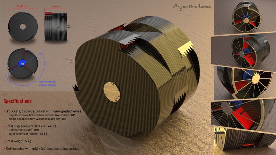
Bucket drum with moving vanes
grabcad
The innovative concept hinges on dividing the drum into multiple internal "chambers" by employing adjustable vanes that control the scoop inlet ports according to the drum's angular position. These vanes are confined to supports on the bucket, allowing them to move only radially within the drum. The movement of the vanes is facilitated by a cam-like profile carved onto a stationary shaft (or camshaft), which is solidly attached to the Rassor chassis and coaxial with the bucket drum. A small wheel, guided along this cam profile, enables the radial motion of a vane, connected to its inner end via a pin that serves as the wheel's rotation axis. The cam profile ensures that inlet ports are opened only during the desired angular interval for regolith collection (clockwise rotation) and regolith dumping (anti-clockwise rotation). A protective cover and seal on the cam guide prevent regolith from obstructing the wheels' movement along the cam profile. This design optimizes the inner drum volume for regolith storage while preventing unintentional expulsion during drum rotation or transportation to the dump location. Additionally, periodic port opening/closing removes mud and obstacles that may accumulate, reducing the risk of clogging. The bucket drum itself is crafted from a thin carbon-fiber layer, with aluminum-alloy supports featuring spokes. The entire system is fully modular, allowing for easy installation of multiple buckets in series. The camshaft is also modular, consisting of individual units that can be assembled to form the complete shaft. This design enables the hosting of bearings that support the main rotating driveshaft. The geared end of this shaft connects to the motor within the Rassor arm, while the other end is secured through screws to the aluminum structure of the outer bucket drum. Each scoop features a steel or titanium "cutting edge" and a grid for collecting small regolith particles. The grid elements are wedge-shaped, cutting through possible mud (in cases where regolith contains ice or water) to prevent clogging. Optionally, the cutting edge may include a backward extension with a "scraping surface" to prepare the excavation area between ports. The proposed final assembly comprises three bucket modules arranged in a row, each containing three scoops. The buckets measure approximately 110 mm in width, resulting in an overall width of 331 mm and an outer diameter of 450 mm. Scoops are spaced at 40° intervals, ensuring that only one scoop is engaged at a time. The useful inner volume of each drum is 14.9 liters, totaling 44.7 liters for the three-bucket assembly. With an expected fill ratio of 80%, this design enables the collection of 35.8 liters of regolith. Excluding the driveshaft and camshaft connection means, the total weight of the assembly is approximately 5 kg. To adhere to the weight limit, the number of bucket units was limited to three, and the total volume is smaller than the maximum allowed. The cutting edge included in the final assembly does not feature a scraping surface for weight compliance. An example of the cutting edge with scraping surface is provided in STL format.
With this file you will be able to print Bucket drum with moving vanes with your 3D printer. Click on the button and save the file on your computer to work, edit or customize your design. You can also find more 3D designs for printers on Bucket drum with moving vanes.