Build Platform Level Test Pattern
thingiverse
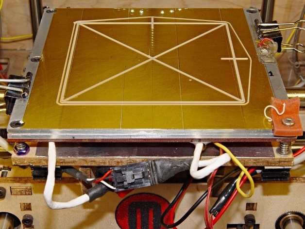
To ensure accurate build platform alignment for successful prints, utilize a thin calibration object measuring 0.25 mm layers that needs to be leveled within +/-0.05 mm across the entire platform. Employ this OpenSCAD program to generate an object with bars one thread tall and two threads wide, which will be converted into G-Code by Skeinforge or your preferred slicer. Printing this short and thin plastic extrusion reveals misalignments. However, remember to modify the OpenSCAD source according to your printing parameters for correct G-Code generation. Measure the bars' thickness with calipers; any discrepancy indicates adjustment requirements at specific screws. Additionally, ensure that the overall printed width of each bar matches the Skeinforge W/T setting and observe the tabs indicating axis directions for corrections. For more information, visit http://softseller.com/2012/01/10/platform-level-test-pattern/.
With this file you will be able to print Build Platform Level Test Pattern with your 3D printer. Click on the button and save the file on your computer to work, edit or customize your design. You can also find more 3D designs for printers on Build Platform Level Test Pattern.