C70 Double Bay Switch-Key
thingiverse
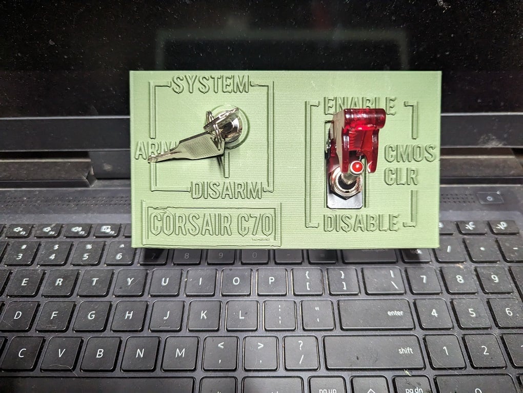
**NOTE:** _This is a remix of [DragonflyFabrication](https://www.thingiverse.com/dragonflyfabrication/designs)'s excellent [Corsair C70 Ignition Key](https://www.thingiverse.com/thing:2748066) project. However, for some reason, Thingiverse's remix source search is not working to pull it up by either name or Thing ID so I can't "officially" credit it as the source of the remix right now which I regret and apologize in advance. I will do my best to correct this in the future if possible._ ---- # Summary This is a double height 5.25" drive bay panel cover with room to add a key switch and lighted toggle switch with a safety cover for additional functionality or modding. This panel was designed and intended for the classic and venerable Corsair C70 full-size ATX case. However, it should work on other case models, both by Corsair and other manufacturers, especially non-OEM makers, assuming the case has room for at least two 5.25" drive bays. **Please be aware I have not actually tested this interoperability. ** If you try it in another case and it works please let me know! --- # Design and Motivation I picked up this case locally because I needed one for a budget gaming rig, the price was right, and it was available. I didn't realize how cool the C70 was or the cult following it had at the time. Although I originally had a different theme and color scheme in mind, because the case is intended to look like a piece of military equipment or an ammo box and looks so cool I decided to lean into this aesthetic. I do not regret it. Since it looks like it is intended to fire missiles, I decided it needed a arm/disarm key switch. I did some research online and realized this was not hardly an original thought and this mod is common for this case. However, as I often do some pretty extreme overclocking and find myself needing to clear the CMOS more often than most, I thought a button or toggle switch attached to the Clear CMOS header would also be cool and landed on a LED-lit toggle switch with a safety cover. These are usually 12v, which can conveniently be tapped from most motherboards. I used the 12V+ pin from the older 4-pin 12V RGB header on my ASUS Prime Z270 board. Alternatively, it could also be powered by 5V using a fan header or 5V aRGB header on newer boards- just bear in mind the LED won't be quite as bright. This might even be a feature for some. Non-affiliate Amazon links and wiring guides for both key switch and lighted toggle are included below. I am also including the link to the [public TinkerCAD project](https://www.tinkercad.com/things/7gSutYryuW5-shiny-jaiks-kieran) to make remixes and mods easier. --- # Future Revisions I may eventually add a display. I think a red or green 7-segment display to the front using the third drive bay space would be very cool. A small VFD or monochrome OLED would also be cool display options. I'm thinking that a boot code display would be cool for that, or possibly a display showing something like CPU utilization,, current clock speed, or package temperature would also be cool options. Maybe even all four with a dial switch to select between the the different choices. However, I haven't sat down to figure out how to get that info to the 7-segment display. I would be fine using a small chip like an ESP32/ESP8266 or something like a Raspberry Pi Pico to process some sort of input, especially since I would need something anyway to drive the 7-segment display and they are good candidates. These chips could definitely be powered off a 12V or 5V header as described above for the toggle switch. Alternatively, one of those cheap M.2/PCI/PCIe diagnostic cards that include a 7-segment boot code display could be hacked for this purpose, or if the motherboard already has a 7-segment display, some quick modding with a soldering iron would allow it to drive the front display as well. However, if possible I'd like to avoid having to run a script or other software on the computer to export the information, as this would add complexity and compute overhead. If you would like to see this as a remix, and/or if you have ideas for how to go about it, please comment and let me know! If you are really into adding more gadgets and buttons and other decorations to the front (which I definitely approve of, especially on this case), you could also add something in like a rotary potentiometer dial to adjust PWN case fans, or some sort of button or other selector combined with a chip like an ESP32/8266 or Pi Pico to control additional LED strips, which could again all be powered from a conventient 12V or 5V header. The possibilities are really nearly endless. --- # Remix Process Essentially, I used the key switch panel from DragonflyFabrication's project Corsair C70 Ignition Key (linked above) as inspiration but, as noted above, I wanted to use both a key switch to "arm" and "disarm" the system and a toggle switch to clear the CMOS since I do a fair amount of overclocking and can put that to good use (plus as a lighted toggle with a safety cover, it just looks cool and martial). Instead of the original key switch panel in the project, I worked from the blank panel file included in the project. I stacked two of them together for a double bay cover to give myself enough room to add both elements, plus text. The text draws inspiration from [a photo I found on Google Image Search](https://cdn2.picryl.com/photo/2013/01/14/sgt-1st-class-mandrill-demps-31st-air-defense-artillery-e2db87-640.jpg) of the control panel for older [Patriot missile batteries](https://en.wikipedia.org/wiki/MIM-104_Patriot). That is exactly the look I am going for with this mod. --- # Assembly ## Key Switch The key switch is a two-terminal model (aka, it only has "on" and "off" modes for simplicity) intended for generic Chinese electric scooter ignition. It is intended for a through-hole of ~10mm. I made it 11mm to account for any tolerance issues caused by the 3d printing process and to allow wiggle room for perfect alignment. If you are using a different switch and want to remove the plate recess or modify the through-hole size, I have included a link to the [public TinkerCAD project](https://www.tinkercad.com/things/7gSutYryuW5-shiny-jaiks-kieran) for easier remixing of the design. The key switch is wired in series with the power button, so the key works to "arm" the system and then the original Corsair C70 power button will then cause the system to boot. ### Key Switch Wiring 1. Motherboard power button header (+ pin) --> Key switch pole 1 2. Key switch pole 2 --> Original C70 power button harness (+ wire) 3. Original C70 power button harness (- wire) --> Motherboard power button header (- pin) **Key switch used:** [Uxcell Electric 2 Position ON OFF Metal Keylock Switch](https://www.amazon.com/dp/B019I12414?psc=1&ref=ppx_yo2ov_dt_b_product_details) (_NOT an affiliate link!_) ## Toggle Switch For added cool factor and military vibes, the toggle switch is LED-lit and has a flip-up transparent plastic safety cover. The switch has three terminals- the normal two for the switch and one terminal for powering the LED. The LED uses 12V+ but as discussed above could also be powered with 5V or even other reasonable voltages, both higher (if using an appropriate resistor) and lower (this will result in slightly dimmer light). The through-hole it uses is ~11mm. The design uses a 12mm hole to account for printing tolerances and alignment adjustments. The switch I used also has a larger plate intended to control torqueing causes by flipping the safety cover up and down, which has a through-hole and is sandwiched between the drive bay cover and the nut and washer for holding the switch in place. I created a slightly oversize recession into the panel for this plate. On the model I used, this plate has the through-hole offset to the OFF side, and the switch post has a small slot that catches a tab that extends into the through-hole to ensure the plater and safety cover are aligned properly. If your switch does not have a safety cover, or the safety cover does not have such a keying system, pay attention to the orientation of the switch whe installing it. If you are using a different switch and want to remove the plate recess or modify the through-hole size, I have included a link to the [public TinkerCAD project](https://www.tinkercad.com/things/7gSutYryuW5-shiny-jaiks-kieran) for easier remixing of the design. The ON and OFF terminals of the switch are wired to the two terminals of the Clear CMOS header on the motherboard. Alternatively, this could instead be wired to the reset button. It should not matter which pin goes to which switch terminal or side of the reset button. Positive voltage is connected to the third terminal on the switch, labelled LED or using the LED symbol. This voltage is generally supplied from a motherboard source such as the positive 12V or 5V pin on the front panel power LED header, a 12V or 5V RGB/aRGB header, or a 5V or 12V fan header. An internal USB 2.0 header or external USB 2.0 port or charger could also be used in a pinch but might require additional wiring. The switch should only light up when in the ON position. ### Toggle Switch Wiring 1. Pin 1 of "Clear CMOS" motherboard header/reset button wire 1 --> Toggle switch OFF terminal 2. Pin 2 of "Clear CMOS" motherboard header/reset wire 2 --> Toggle switch ON terminal 3. +12V/+5V from motherboard header or other source --> Toggle switch LED terminal **Toggle switch used:** [ESUPPORT Car Red Cover Red LED Toggle Switch](https://www.amazon.com/dp/B00SOENYUC?psc=1&ref=ppx_yo2ov_dt_b_product_details) (_NOT an affiliate link!_) --- # Assembly and Installation 1. Connect appropriate wires to each of the three terminals of the toggle switch- do not connect to motherboard 2. Remove the top nut and safety cover plate from the post of the toggle switch 3. Insert the toggle switch through the panel's through-hole from behind- pay attention to switch orientation 4. Place the safety cover plate over the switch post and into the recessed groove- pay attention to switch orientation 5. Screw on the top nut tightly onto the toggle switch post to lock the switch into place- thread locking compound (Loctite, etc.) or other glue can optionally be used sparingly 6. Connect appropriate wires to each of the two terminals of the key switch- do not connect to motherboard or case power switch 7. Remove the bottom nut from the post of the key switch 8. Insert the key switch through the panel's through-hole from the front- pay attention to switch orientation 9. Screw on the bottom nut tightly onto the key switch post to lock the switch into place- thread locking compound (Loctite, etc.) or other glue can optionally be used sparingly 10. Press the drive bay cover panel firmly into place from the front of the case 11. Ensure panel is aligned correctly and flush with front of case- you may need to also reach through the inside of the case- glue can optionally be used sparingly 12. Route wires as appropriate 13. Connect wires as described in the above wiring diagrams 14. Test 15. Optional: Lightly paint letters on cover (white or black would be good choices, as would adding glow-in-the-dark pigment), or use Sharpie marker or paint pen --- # Builds and Remixes I would love to see builds of this project if anyone actually finds it useful (which I kind of doubt if I am being honest). I am posting pictures of two prints I did. On the first, the key switch hole looks ragged because I originally designed it exactly to the 10mm spec and tolerances were such that the post would not quite fit through the hole. I tried to widen it but it looked very ugly so I revised the design to make the hole 1mm larger and reprinted. I think it came out very good. I am happy to make small changes if they are within my limited CAD skills, such as widening the holes. Just ask! I am also including a link to the [public TinkerCAD project](https://www.tinkercad.com/things/7gSutYryuW5-shiny-jaiks-kieran) for easier remixing of the design. Just ungroup the main project to get at various elements. I would also love to see any remixes of this design or get your suggestions for additional features or changes that would make this even cooler. This is especially true for adding a display such as a 7-segment LED array or a small VFD or monochrome OLED as discussed above. Ideas for what information to put on this display and how to get this info to the display from the system are very welcome. As I said, I would prefer to do something directly from the motherboard to avoid complexity and overhead, but I'm a professional software designer so I do think an internal USB 2.0 header getting serial data from a small app or script could be an option. This is easier for a Linux system but possible in Windows as well (don't ask me about Mac, I have no idea!). --- # Printing I printed this design on my Creality Ender 5 Pro. I do have the Gulfcoast Robotics all-metal hotend but otherwise the printer is stock. I used 1.75mm Olive Green Hatchbox Matte PLA. It did not quite match the color, and I may repaint, but I think it's still pretty good. I am very impressed with the quality of this filament and love the matte look. I may also give it a matte clear coat to better protect it from stains and marks and prevent any layers from peeling. **Filament used:** [Hatchbox Matte PLA, Olive Green](https://www.amazon.com/dp/B09G8DBZFY?psc=1&ref=ppx_yo2ov_dt_b_product_details) (_NOT an affiliate link!_) For the second (and final for now) build, I sliced in Cura using the following settings: - Layer Height: 0.2mm - Infill: 80%, Tri-Hexagonal (you could probably get away with much less but I like the heft and resistance to flex) - Support: everywhere, 25% density, 45° overhang - Temp: 60° plate, 215° nozzle (it's winter and we also keep our house cold, plus there are several fans in the room, so the printer tends to run cool) - Speed: 80mm/s - Walls, Top, Bottom: 4 layers/lines, 0.8mm thinkness - Adhesion: Raft, 40mm/s I do recommend the supports, but you might get away without them if your printer is very dialed in and can do reasonable bridges, as the largest unsupported overhangs are the insides of the 12mm holes for the switches. --- **That's it! Please comment if you have any suggestions or questions. I hope this projects helps you do some cool and exciting case mods. Thanks for checking my project out, and feel free to check out my other projects at the link below!** -_Bill Boyles)_ - [southern_magilla](https://www.thingiverse.com/southern_magilla/designs)
With this file you will be able to print C70 Double Bay Switch-Key with your 3D printer. Click on the button and save the file on your computer to work, edit or customize your design. You can also find more 3D designs for printers on C70 Double Bay Switch-Key.