Cable management box for Ender 5 Plus
thingiverse
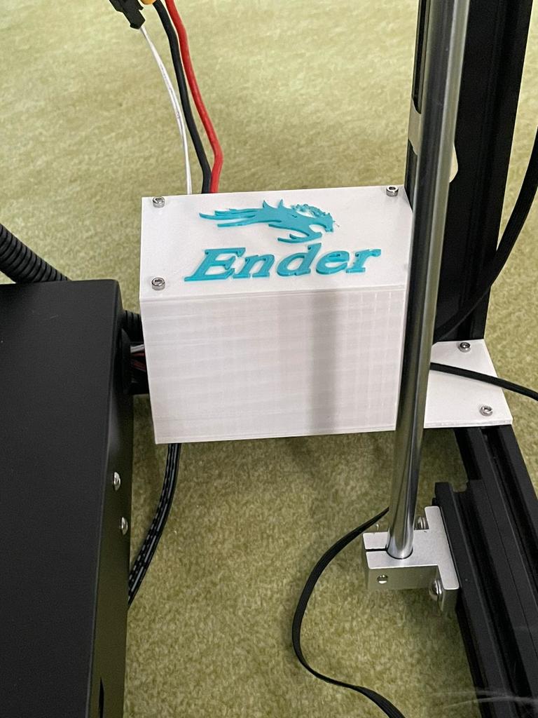
Hallo, habe zwei verschiedene Kabelboxen entworfen, um den Kabelsalat beim Ender 5 Plus dezent zu verstecken. Es gibt in der Box verschiedene Öffnungen. Die 2 Öffnungen die sich im Boden befinden sind für die Z-Achsen Motoren links und rechts. Die 2 seitlichen Öffnungen die sich links befinden: die größere Öffnung ist dafür da, dass alle Kabel in die Box kommen. Die kleinere Öffnung ist dafür da, dass die Hotendkabel aus der Box geführt werden. Die kleine rechteckige Öffnung links oben ist für die Heizbettkabel. Die kleine rechteckige Öffnung rechts oben, unter der Verschraubung ist dafür da, dass man die Kabel vom Extruder, Filament Sensor, Y-Motorkabel und das Kabel für den Y-Sensor in den Rahmen verlegen kann. Das rechteckige Loch auf der rechten Außenseite ist für das Kabel für den X-Motor und für den X-Sensor. Ich habe versucht, so weit wie möglich mit Bilder alles zu dokumentieren. Für den Deckel werden 4 x M3x5 Schrauben benötigt. Für die Befestigung der Box im Rahmen werden 4 Stück M3x6 Schrauben benötigt und 4 M3T Muttern/Nutensteine. Version V1 ist die kleine Box. Dazu zählen der Deckel V1 und das Logo V1. Man kann den Deckel auch ohne Logo drucken oder man fügt das Logo einfach mit dem Deckel in Cura zusammen. Falls man das Logo in einer anderen Farbe drucken möchte, der Deckel hat ein Höhe von 2,5mm. Oder man druckt das Logo extra und klebt es mit einem Kunnststoffkleber an den Deckel. Version V2 ist die größere Box. Hierzu zählt der Deckel V2 und das Logo V2. Für den Druck des Logos gilt das Gleiche wie für die Variante V1. Hello, I designed two different cable boxes to discreetly hide the tangled cables on the Ender 5 Plus. There are different openings in the box. The 2 openings in the bottom are for the Z-axis motors on the left and right. The 2 side openings on the left: the larger opening is there for all cables to come into the box. The smaller opening is there for the hotend cables to be led out of the box. The small rectangular opening on the top left is for the heating bed cables. The small rectangular opening at the top right, under the screw connection, is there so that the cables from the extruder, filament sensor, Y-motor cable and the cable for the Y-sensor can be laid in the frame. The rectangular hole on the right outside is for the cable for the X-Motor and for the X-Sensor. I tried to document everything with pictures as much as possible. 4 x M3x5 screws are required for the cover. 4 M3x6 screws and 4 M3T nuts / slot nuts are required to fasten the box in the frame Version V1 is the small box. This includes the cover V1 and the logo V1. You can also print the lid without a logo or you can simply put the logo together with the lid in Cura. If you want to print the logo in a different color, the lid has a height of 2.5mm. Or you can print the logo separately and stick it to the lid with a plastic adhesive. Version V2 is the bigger box. This includes the cover V2 and the logo V2. The same applies for printing the logo as for variant V
With this file you will be able to print Cable management box for Ender 5 Plus with your 3D printer. Click on the button and save the file on your computer to work, edit or customize your design. You can also find more 3D designs for printers on Cable management box for Ender 5 Plus.