cablechain adapter Anycubic Mega S
thingiverse
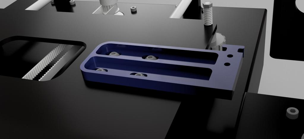
Cable chain adapter for Anycubic and 7x7 or 7x15mm cable chains ==================================================== Mein Problem mit dem Anycubic Mega S war, dass die Kabel zum Heatbed mit einem Kabelbinder an der rechten hinteren Stellschraube angebracht waren. damit war der Kabelbruch eigentlich nur eine Frage der Zeit. Ich hatte dann lange Zeit einfach den Kabelbilder entfernt und die Kabel lose hinter dem Drucker hängen lassen, das habe ich jetzt korrigiert. Für die X-Achse habe ich den Ansatz vom Projekt [Anycubic i3 Mega X-Carriage](https://www.thingiverse.com/thing:3537449) verwendet, für den Tisch haben mir die vorhandenen Lösungen nicht gefallen. Ich will die Kabelkette nicht nach hinten raus laufen lassen, da sie dort in der Luft hängt und zudem die Bautiefe des Druckers erkennbar vergrößert, also muss sie parallel zum Tisch nach vorne laufen. Achtung: Es gibt für den Anycubic i3 zwei verschiedene Tische: Der eine hat 220mm Breite und der andere 240mm. Ich habe 240mm und somit wurde der Platz an der Seite nochmal um 10mm geringer. Ich habe eine 7x7 Kette gekauft (ich spare mit den Link, der in 2 Monaten eh ins nichts führt) und bei erster Prüfung passte es. Hier also meine Lösung mit folgenden Vorteilen: - "Footprint" des Druckers wird eher kleiner als größer - Vorhandene Kabel können ohne Nacharbeit verwendet werden - Kabelschlepp ist sehr kurz - Nur ein Druckteil Das habe ich mir mit folgenden Nachteilen erkauft: - Bohrarbeit am Gehäuse - vordere rechte Tischklemme der Ultrabase scheuert leicht an der Kette Hier die BOM: - Schleppkette 7x7 50cm reichen + 2x Kabelschuh. - Bohrer 3,5mm oder 4mm für die Schraubenlöcher der Kette im Gehäuse - Bohrer 6mm und 9mm (ich bohre in zwei Stufen) für das neue Kabelloch im Gehäuse - 1-3 kleine Kabelbinder - optional: Heißkleber für die Sicherung des Sensorkabels - Optional: Wer seine Tisch Unterseite bisher noch nicht isoliert hat, sollte das bei der Montage gleich mit machen. Die Isolierung der Tischunterseite reduziert die Heizzeit erkennbar und der Tisch kann höhere Temperaturen erreichen! Meine Empfehlung! Montage: ------------ Erster Schritt bei eingeschaltetem Drucker: Z-Position des Druckkopfes ganz nach oben fahren oder zumindest 10cm über den Tisch. Dann den Adapter ausdrucken. Material sollte PET-G sein, wegen der nahen Heizung des Heatbeds. ich empfehle, bei der Montage gleich eine Isoliermatte mitbestellen und einbauen (siehe Option oben). Nächster Schritt ist das Abklemmen des Kabelstrangs am Mainboard. Dazu das Gehäuse unten öffnen und die Kabel für die Heizung und den Temperatursensor abziehen. Für den Sensor müsst ihr die klebrige Sicherung entfernen. Eventuelle Kabelbinder durchschneiden und die Kabel durch das kleine Loch im Gehäusedeckel noch oben raus ziehen. Jetzt den Tisch komplett demontieren, also alle Stellschrauben raus schrauben und den Tisch nach oben abheben. Die schwarze PVC-Ummantelung des Kabelstrangs entfernen (ist meistens eh schon komplett durchlöchert). Ihr solltet den Tisch jetzt lose in der Hand halten. An dieser Stelle will ich nochmal drauf hinweisen, was für ein riesiger Unterschied besteht, die Ultrabase-Glasscheibe gegen einen Alu-Tisch mit Auflage (PEI oder FP4) zu tauschen! Ich habe eine 5mm Aluplatte ("Gussplatte Feingefräst" oder jede andere ebene Aluplatte) drauf gepackt und der Unterschied ist grandios! Entgegen der üblichen Vorgehensweise habe ich die Ultrabase Heizung mit M3 Transferfolie (die dünnste, die es gibt) von unten an die Platte geklebt und oben drauf (ebenfalls geklebt) eine sehr dünne FP4 Scheibe. 3 Daumen hoch! Wer also Lust hat und die Anleitung erst einmal durchliest, sollte die Bestellung einer Platte + 2x Transferfolie dünn + 1x Oberfläche PEI oder FP4 erwägen! Schleichwerbung: Ein wehrhafter Landmann verkauft hier gute Qualität zu vernünftigen Preisen! Jetzt werden die vier Schrauben des hinteren rechten Tischlagers entfernt. Der Adapter wird über das Lochbild gelegt und angeschraubt. Achtung: Wer den ersten Layer mit mehr Fluss druckt (so wie ich), der könnte die Löcher zunächst noch etwas entgraten, die Schrauben sitzen sonst etwas stramm. Schrauben wieder eindrehen, aber nicht fest ziehen. Das Adapter sollte sich (schwer!) nach links und recht verschieben lassen. Damit machen wir gleich die Einstellung: Den Tisch wieder in die passenden Löcher einsetzen und den Adapter soweit verschieben, dass zwischen Tisch und Adapter 1-2mm Luft sind. Tisch wieder runter und Schrauben fest ziehen. Jetzt den Kabelschlepp anpassen: bei mir sind es 13 Kettenglieder, je nach Position des Durchgangsloches. Achtung: Am Adapter kann man entweder den Kettenschuh verwenden oder ein Kettenglied mit Kabelbinder befestigen. Wenn der Kettenschuh zu viel Bewegung nach "oben" zulässt, steht die Schleppkette nachher neben dem Tisch und kann mit dem Druckkopf kollidieren! Deswegen habe ich ein Kettenglied als Start verwendet, siehe Bild. Alles mal anhalten und prüfen, wo der untere Kettenschuh landen soll, dann Kette entsprechend kürzen und die Bohrlöcher auf dem Gehäuse markieren: Die 2x 3,5mm Löcher sind vorgegeben durch den Kettenschuh, das Durchgangsloch würde ich 2-4cm hinter den Kabelschuh bohren. Keine Angst, der Platz in Höhe der X-Achse im Gehäuse ist leer. Jetzt die X-Achse vom Gehäuse lösen. Das sind auf jeder Seite 4xM5 Zylinderkopfschrauben. Die Achse muss nur etwas gekippt werden, damit man mit dem Bohrer dran kommt. Löcher bohren und entgraten. Zusammenbau: Jetzt die Kabel durch die Kette fädeln. Kette am Adapter (oben) befestigen (Schuh oder Kettenglied). Am T-formigen Nippel des Adapters kommt ein Kabelbinder hin, der das Kabel fixiert. Kette unten befestigen und Kabel durch das Durchgangsloch nach innen fädeln. Innen wieder "aufräumen", die Heizung an die Platine schrauben, den Sensor einstecken und mit einem Tropfen Heißkleber fixieren. Gehäuse schließen und Tisch wieder montieren. Das war's. Cable chain adapter for Anycubic and 7x7 or 7x15mm cable chains ================================================== == My problem with the Anycubic Mega S was that the cables to the heatbed were attached to the right rear set screw with a zip tie. so the cable break was actually only a matter of time. For a long time I simply removed the cable picture and left the cables hanging loosely behind the printer, I have now corrected that. For the X-axis I have the approach from the project [Anycubic i3 Mega X-Carriage](https://www.thingiverse.com/thing:3537449) used, I didn't like the existing solutions for the table. I don't want the cable chain to run out to the back, because it hangs in the air there and also noticeably increases the overall depth of the printer, so it has to run parallel to the table to the front. Attention: There are two different tables for the Anycubic i3: One has a width of 220mm and the other 240mm. I have 240mm and thus the space on the side was reduced by another 10mm. I bought a 7x7 chain (I save with the link, which will lead to nowhere in 2 months anyway) and it fit at the first test. So here is my solution with the following advantages: - The printer's "footprint" is getting smaller rather than larger - Existing cables can be used without rework - Cable tow is very short - Just a printed part I bought this with the following disadvantages: - Drilling work on the housing - the front right table clamp of the Ultrabase rubs slightly on the chain Here is the BOM: - cable chain 7x7 50cm should be more than you need. - Drill 3.5mm or 4mm for the screw holes of the chain in the case - Drill 6mm and 9mm (I drill in two stages) for the new cable hole in the case - 1-3 small cable ties - optional: hot glue for securing the sensor cable - Optional: Anyone who has not yet insulated the underside of the table should do so during assembly. The insulation of the underside of the table noticeably reduces the heating time and the table can reach higher temperatures! My recommendation! Assembly: ------------ First step with the printer switched on: Move the Z position of the print head all the way up or at least 10 cm above the table. Then print out the adapter. Material should be PET-G because of near heating of heatbed. I recommend ordering and installing an insulating mat during assembly (see option above). The next step is to disconnect the wiring harness on the mainboard. To do this, open the bottom of the housing and pull off the cables for the heater and the temperature sensor. For the sensor you have to remove the sticky fuse. Cut through any cable ties and pull the cables out through the small hole in the housing cover. Now dismantle the table completely, i.e. unscrew all adjusting screws and lift the table upwards. Remove the black PVC sheathing of the wiring harness (it's usually already completely perforated). You should now be holding the table loosely. At this point I would like to point out again what a huge difference it is to exchange the Ultrabase glass pane for an aluminum table with a support (PEI or FP4)! I put a 5mm aluminum plate ("finely milled cast plate" or any other flat aluminum plate) on it and the difference is terrific! Contrary to the usual procedure, I glued the Ultrabase heater with M3 transfer foil (the thinnest available) to the plate from below and on top (also glued) a very thin FP4 disc. 3 thumbs up! So if you feel like it and read the instructions first, you should consider ordering a plate + 2x thin transfer foil + 1x surface PEI or FP4! Surreptitious advertising: A well-fortified farmer sells good quality at reasonable prices here! Now the four screws of the rear right table bearing are removed. The adapter is placed over the hole pattern and screwed on. Attention: If you print the first layer with more flow (like me), you could deburr the holes a bit first, otherwise the screws would be a bit tight. Screw the screws back in, but do not tighten. The adapter should be able to be moved (difficult!) to the left and right. With that we make the adjustment right away: Put the table back into the appropriate holes and move the adapter so far that there is a gap of 1-2mm between the table and the adapter. Lower the table and tighten the screws. Now adjust the cable tow: I have 13 chain links, depending on the position of the through hole. Attention: You can either use the chain shoe on the adapter or attach a chain link with a cable tie. If the chain shoe allows too much "upward" movement, the drag chain will be next to the table and can collide with the print head! That's why I used a chain link as a start, see picture. Stop everything and check where the lower chain shoe should land, then shorten the chain accordingly and mark the drill holes on the housing: The 2x 3.5mm holes are given by the chain shoe, I would drill the through hole 2-4cm behind the cable shoe. Don't worry, the space at the level of the X-axis in the housing is empty. Now detach the X-axis from the housing. There are 4xM5 cylinder head screws on each side. The axis only has to be tilted a little so that you can get to it with the drill. Drill and deburr holes. Assembly: Now thread the cables through the chain. Fasten the chain to the adapter (above) (shoe or chain link). A cable tie is attached to the T-shaped nipple of the adapter, which fixes the cable. Fasten the chain at the bottom and thread the cable inwards through the through hole. "Clean up" the inside again, screw the heater to the circuit board, plug in the sensor and fix it with a drop of hot glue. Close the housing and reassemble the table. That's it.
With this file you will be able to print cablechain adapter Anycubic Mega S with your 3D printer. Click on the button and save the file on your computer to work, edit or customize your design. You can also find more 3D designs for printers on cablechain adapter Anycubic Mega S.