Calibrate X Y Z
cults3d
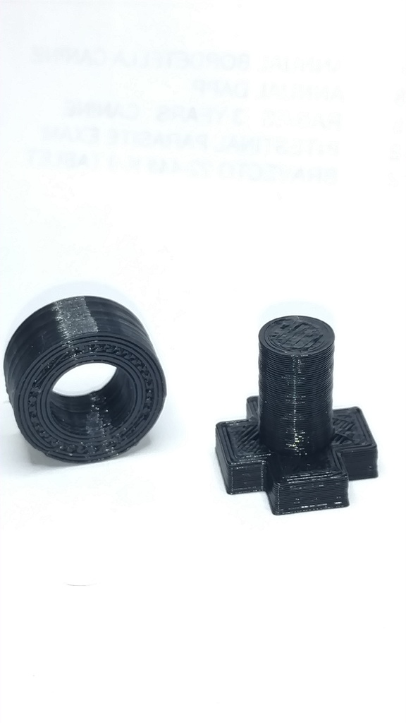
I created these prints so I could quickly and easily calibrate my X, Y, and Z axis. The process for calibration is to first print the "calibration test" file. I suggest printing this with conservative settings (slower speeds and thinner layers will yield more accuracy). Second take the measurements of the all the axis of the print (the included drawings list the dimensions of the parts). Then use this formula to calculate your new value for the E Steps. Desired Measurement / Actual Measurement X Current E Step Value = New E Step Value For example, the measurement of the z axis is 19.86mm and the current E Step value is 80. 20 / 19.86 x 80 = 80.56 Adjust the value in your firmware or printer controller to the new Z axis E Step value of 80.56. Repeat the process the remaining axis. You can change the E Step value in the printer controller or in the printer firmware. There are so many YouTube videos on how to do this I couldn't recommend just one. My advice is watch several of them until you feel comfortable with the process. Use the "Calibration Circle" file to adjust the "horizontal expansion" setting in your slicer. If your not sure what that is, changing the "horizontal expansion" setting allows for adjustment for circles/hole printing flat so they are true to dimension. This is for calibrating at a small scale. That is, it is accurate within the size of the print sample. If you calibrate with this sample, then print something 10 times bigger, most likely the calibration will be off. So my advice is to adjust the size of your calibration objects to the approximate size you will be printing. Or you could just do the whole bed and be done. I am not that patient.
With this file you will be able to print Calibrate X Y Z with your 3D printer. Click on the button and save the file on your computer to work, edit or customize your design. You can also find more 3D designs for printers on Calibrate X Y Z.