Calibrate your 3D printer to print parts to fit
thingiverse
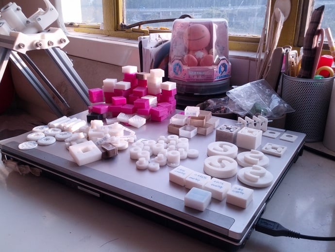
( Just in case the text formatting were jerked up, the article in PDF format is available at http://www.thingiverse.com/download:2091544 ) I have my Thing-O-Matic for a year now. From time to time, I tried to calibrate it to print parts to fit. Finally, I got it done (See http://youtube.com/watch?v=lQbvfiZAm-c). It turns out I just had the edge width and the scaling wrong. If you also have the problem to print parts to fit, read this article. It might work for you too. Here are the symptoms of the problem I'm trying to fix. 1) A printed plug is impossible to fit into its printed hole. 2) Small parts (around 1 cm size) are too big, while larger parts (around 10 cm size) are too small. Instructions Okay okay, let's see what our 3D printers should be offering first (if configured correctly). See http://www.youtube.com/watch?v=lQbvfiZAm-c . The video shows two parts, an S-Shape hole and an S-Shape plug http://www.thingiverse.com/download:141737 . The plug and the hole are edge to edge touching each other in the STL file. As show in the video, I can actually plug them together just by pushing real hard with bare hands, no tolerance compensations in the design, no drilling or filing, they just fit. The S-Shape is chosen deliberately as it shares a lot of common features with interlocking designs. Designing is fun with interlocking designs. ( A more fancy result, same premise, http://www.youtube.com/watch?v=O3dJsjv-8vA ) This article is intended for Skeinforge (SF) calibration, and I did my calibration with ABS plastics, Thing-O-Matic (0.4mm nozzle, firmware 4.1) and ReplicatorG+Skeinforge 50. Before the calibration Temperature will affect the actual amount of the extruded plastics and, therefore, the realized line width. Though it is not necessary, I strongly recommend you to figure out the strongest bonding temperature initially, see http://www.thingiverse.com/thing:35088 . You really need every bit of available bonding strength for printing large ABS objects. If you are using ReplicatorG, please disable its user interface "Use Print-O-Matic". This named-funny-UI is just to override some Skeinforge variables without your notice. It is easier to calibrate your 3D printer to fit without this named-funny-UI . You can do it by unchecking the checkbox "Use Print-O-Matic (stepper extruder only)" in the "Generate Gode" window (See http://thingiverse-production-new.s3.amazonaws.com/assets/95/f2/da/5d/af/disable_replicator_setting.png ). If you insist to use the user interface "Use Print-O-Matic", you won't be able to adjust the infill width such that you would end up with a fragile printout (See Section Calibrate infill). Here is the list of necessary variables for this calibration to work, Carve/Extra Decimal Places (float) : change to 5 Carve/Edge Width over Height (ratio) : nozzle diameter/layer height Inset/Infill Width over Thickness (ratio) : nozzle diameter/layer height (initially) Dimension/Filament Packing Density (ratio) : needs calibration (equivalent to the reciprocal of the extrusion multiplier in Slic3r) Scale/XY Plane Scale (ratio) : needs calibration Before the calibration, you need to increase Carve/Extra Decimal Places (float) to 5. This variable is to control the significant digits of the values in a gcode file. There is no point to reduce precision at this point. Precision is king if you want to print parts to fit. Calibrate line width If you are having problems to print parts to fit, your 3D printer is probably drawing lines wider than Skeinforge expecting. In my case, SF is expecting 0.4mm, while my 3D printer is drawing 0.64mm (See http://thingiverse-production-new.s3.amazonaws.com/assets/b9/49/7b/db/d0/IMG_20130225_124259a.jpg ). The optimal line width that your 3D printer can do is the same as its nozzle diameter, so you want to enforce that to optimize its ability to print small features. To calibrate the line width to optimal, 1a) set both "Carve/Edge Width over Height (ratio)" and "Inset/Infill Width over Thickness (ratio)" to "nozzle diameter/layer height". 1b) set both "Speed/Feed Rate Setting (float)" and "Speed/Flow Rate Setting (float)" to the same value. 2) print the thin wall model http://www.thingiverse.com/download:259710 , and measure the wall thickness with a caliper. 3) adjust "Dimension/Filament Packing Density (ratio)". 4) repeat Step 2 and Step 3 until the measured wall thickness meet the nozzle diameter. As a starting point, the new value can be estimated by (measured width)/(nozzle diameter) x (old value) . The goal of this section is to fine tune the volume of the extruded plastics to match the expected line width. Therefore, Filament Packing Density (ratio) is not the only option. There are a brunch of variables which can alter the realized line width, e.g. e-step per mm , changing the flow rate relatively to the feed rate, etc... . Just pick one and stick to it. It probably can work just fine. Just to remind you: when the amount of extruded plastics is too little, it will not make the wall thickness smaller than the nozzle diameter. Instead, you will have some spongy like walls with wall thickness roughly the same as the nozzle diameter (See http://thingiverse-production-new.s3.amazonaws.com/assets/3a/04/82/c9/c7/wall_calibrate.png ). If it is simply impossible for you to calibrate the wall thickness to the nozzle diameter, you may substitute the nozzle diameter by a bigger value (say 0.1mm bigger) and try again. Calibrate scale Once you have the line width right, you can go on to calibrate the scale, here is the procedure: 1) Print the 20mm test cube http://www.thingiverse.com/download:139958 2) Measure the size of the cube with a caliper (CAUTION: measurements must be done after the cube fully cool down) 3) Divide 20mm by the measured size, and set the value to Scale/XY Plane Scale (ratio). The measured size should become approximately 0.5% to 1% smaller than 20mm after the line width calibration, http://thingiverse-production-new.s3.amazonaws.com/assets/f3/c5/51/32/08/scale_calibrate.png . This difference is probably caused by the plastic shrinkage, which can be fixed by adjusting the xy scale. After the scaling calibrated, the ability of your 3D printer to print parts to fit should have improved dramatically. You can print the test plug http://www.thingiverse.com/download:139973 or the S-Shape plug http://www.thingiverse.com/download:141737 to verify. ( Note that, the S character in the S-Shape plug is not symetric. Fitting the S character upside down won't fit ) Please be reminded that, even after the line width and the scaling calibrated correctly, smaller holes (diameter smaller than 3mm) will still be too small due to the arc issue http://reprap.org/wiki/ArcCompensation . The Skeinforge Stretch plugin can handle the arc issue, and gets the smaller holes to fit. The Stretch plugin worths a shot, just enable it to try. The default setting is a little bit conservative. You might need to adjust "Stretch/Perimeter Inside Stretch Over Perimeter Width (ratio)". The default value is 0.32, and I need to increase it to 0.72 to get a perfect 2mm diameter hole. Calibrate infill If you did follow my instructions and reached here, you might have noticed something undesirable. The 20mm cube (15% infill) becomes very fragile (appliable to any non 100% infill objects). We can fix it by decreasing Inset/Infill Width over Thickness (ratio). The new value ... Inset/Infill Width over Thickness (ratio) : (nozzle diameter - overlap)/layer height In particular, I need 0.01mm overlap to enforce the infill lines to fuse with their siblings for 15% infill (of course, 0mm overlap for 100% infill). Note that, the ReplicatorG UI "Use Print-O-Matic" won't allow you to make this change; please, give up that UI. The reason to the fragile printout is that: when you calibrate your line width, the surface beneath is rock solid; while the surface beneath infill is sparsely filled. Without a solid surface to support, the infill lines become narrower. Filling up areas with lines too narrow, we have the infill lines loosely bonded to their siblings, i.e. fragile. You might be confused by the suggested change; indeed, you should be confused. The naming of edge width and infill width are awkwardly misleading. Both named after width, but behave in opposite manners. When you increase edge width, SF will extrude more plastic to realize the increased width, and spaces the lines accordingly. On the contrary, when you increase infill width, SF WILL NOT change the extrusion rate, but it will still do the spacing with the increased line width... (whatever...). Let me translate it for you. Edge width means the width of lines literally, but infill width means line spacing instead. So, if the infill lines are too far from their siblings, we decrease infill width (i.e. line spacing). In case you really need some extra strength, you can consider using wider lines for printing. You can do it by simply setting (no need to calibrate line width again) Carve/Edge Width over Height (ratio) : your desired width / layer height Inset/Infill Width over Thickness (ratio) : (your desired width - overlap) / layer height Don't worry, using wider lines is perfectly fine if Skeinforge knew it. Something counter intuitive about the calibration There is one thing worth noting that my 20mm cube before the line width calibration is actually closer to 20mm in size (See http://thingiverse-production-new.s3.amazonaws.com/assets/f3/c5/51/32/08/scale_calibrate.png ). This is a little bit counter intuitive. What really happening is that ABS plastic will shrink (a lot) after they cool down. So, if the dimension is right before any scaling, the size of a printed object should always be smaller than we expecting (See the second graph). We can also see why it is so using the first graph. In the ideal scenario, the mapping between the ideal size and the expecting size is a line with a 1:1 slope. The wider than expecting realized lines shifts the mapping upward, and shrinkage makes the slope less steep, so we have a small range of good mapping near the intersection (See the first graph). ^^"... a small range of good mapping is probably the most devastating form of misleading clues ever possible. Two popular wrong interpretations By the way, I would like to clarify two popular wrong interpretations of the problem. When I look for reasons for the symptoms above in the internet (See Thing_Info/Description), I keep seeing people saying it is caused by "plastics shrinkage" or "the arc issue" http://reprap.org/wiki/ArcCompensation . For "plastics shrinkage": its true that plastics will shrink after they cool down, so a printed hole (e.g. http://www.thingiverse.com/download:139973) will become smaller. However, its printed plug will also shrink by the same amount. Therefore, a printed plug should fit into its printed hole regardless of shrinkage. For the arc issue http://reprap.org/wiki/ArcCompensation : it will only affect smaller holes, not the larger one. The author is too conservative when he deduces the implications of the formula in the page. ABS plastics can tolerate a tiny bit of deformation. From my experience, if you try to fit a metal rod into a smaller ABS hole, as long as the difference in diameter is within 0.05mm, a fit will still be feasible (the tightness will vary though). To make it easier to read, I re-parsed the table (see http://www.thingiverse.com/download:139948 ). It shows that a 10mm diameter hole will be 0.008mm smaller than it should be, which is not enough to cause a tolerance problem. To a pair of hole and plug, the arc issue will only become a problem unless the diameter is smaller than 3mm. This is it. The information mentioned here is probably mentioned somewhere else already. I just meant to put them in an organized manner as a note for myself. If I missed a citation, please show me. I'll put it back. Yours faithfully, Gary PS: 2013-05-01 - My 3D printer is delivering printouts reliably with precision and strength for quite a while now. It's time for me to say goodbye to test shapes. For the time being, I kept a small portion of the test shapes I printed for some good reasons. This is the last picture of them before I throw them all away, http://thingiverse-production-new.s3.amazonaws.com/assets/be/9a/23/9c/e8/IMG_20130501_070417.jpg . Cheers, fingers crossed... Troublesome shooting Why the wall thickness didn't change after modifing the Dimension/Filament Packing Density (ratio)? Did you press "Save all" after editing profile? Did you re-generate G Code file after editing profile? Are you using the profile you edited in the "Generate GCode" window? Are you using Skeinforge 50 and the latest firmware? Do I need ReplicatorG for this calibration to work? No, you don't need ReplicatorG. This article is intended for Skeinforge 50, not ReplicatorG. You just need Skeinforge for this calibration to work. ReplicatorG is not necessary at all. There are two thin wall models. Which one should I use? Use the one matches your expecting line width. (e.g. 0.4mm line width vs. 0.4mm thin wall; 0.5mm line width vs. 0.5mm thin wall) Both should should be just fine initially. However, when you calibrate the infill width to a smaller value, SF might think the thin wall model should be filled (which can mess up your measurement). Using a matched thin wall model can stop SF from filling the wall. Will this method work with older versions of Skeinforge? Cautiously, yes. For the older versions of Skeinforge, the ways to adjust the realized line width is limited to "changing the feed rate relatively to the flow rate" or "messing directly with e steps per mm". ... (there is no point to stick to the older versions anyway. why bother?)
With this file you will be able to print Calibrate your 3D printer to print parts to fit with your 3D printer. Click on the button and save the file on your computer to work, edit or customize your design. You can also find more 3D designs for printers on Calibrate your 3D printer to print parts to fit.