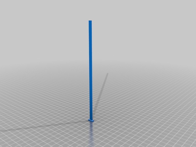
Calibration and Height Test Targets

Calibration and Height Test Targets

thingiverse

The 20mm x 20mm x 210mm rectangular tube was modelled to test out my PrintrBot Simple V2 after a custom mod to expand the Z axis. A shorter version, the 20mm x 20mm x 10mm with 2mm walls, is used to test/calibrate the X, Y, and Z axis. The 182mm tower test printing a narrow tower(solid). Instructions Just download the STL files and slice them in your slicer of choice with your desired settings, then print. The axis calibration can be done by the following: Get your current steps per mm for a given axis. Measure the printed output from the 20x20x10 object for the given axis. Apply the following formula: ( original steps per mm * 20 ) / ( measured dimension ) The result is your new steps per mm that you should use for that axis. Repeat for each axis. An example: You query your printer with the following GCODE: M501 On the PrintrBoard, this will return various values, including the steps per mm for each axis: Steps per unit: M92 X84.40 Y84.40 Z2525.00 E96.00 Let's say for your given printer, you have 84.40 steps per mm for your X axis. You print out the 20mm x 20mm x 10mm target. When you measure the X dimension of the object, you find that the measurement is 20.80mm. ( 84.40 * 20 ) / 20.80 = 81.15384 So, you enter this new value to be saved to the EEPROM on your PrintrBoard: M92 X81.15384 M500 To confirm: M501

Download Model from thingiverse

With this file you will be able to print Calibration and Height Test Targets with your 3D printer. Click on the button and save the file on your computer to work, edit or customize your design. You can also find more 3D designs for printers on Calibration and Height Test Targets.