Camera Mount for bare USB Webcam Board (v3)
thingiverse
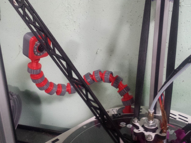
Version three of my efforts to design a chassis and goose neck supporting a webcam for 3d printers. With version 3, I think I've got some standardized connections that should allow me to redesign parts in the future without needing to change everything. This design is made with a bare board camera in mind. Many of these cameras seem to have a standard mounting that will fit nicely inside this mount. Here is one at Amazon.Com that I am using on my own Rostock Max: http://www.amazon.com/180degree-Fisheye-1080p-Angle-Camera/dp/B00LQ854AG I am using my design for a ball and socket joint with a locking ring for the goose neck. These appear to be working well, but I may end up redesigning these at some point in the future to improve the grip further. If I do, I'll still use the threaded top ball to make it compatible with any other designs I make. Here is a link to this design, but I've included the parts in this build as well: http://www.thingiverse.com/thing:1393617 Use as many of the ball and socket joints as you like to make the proper length and flexibility for your goose neck. I have created three different types of camera chassis backs as well as two different types of camera chassis fronts. Choose one of each to suit your own purposes. For camera backs, my initial version is 15mm thick, which fits a board camera with enough room for wiring as long as you remove any connectors from the board camera and subsequently solder the USB wires directly to the board. Some people may not want to do that, so I also created one that is 20mm thick which would allow the camera board to fit without the need to remove the connector. Additionally, the thicker version allows a little extra room in case you find a need to stuff additional components inside. The third camera back may fit the Raspberry Pi's camera module. I don't have one myself to test, so this one is questionable. If it works for you, please tell me. This design requires four additional small screws to secure the Raspberry Pi camera module directly to the camera back, since the holes don't match up with the ones on the USB camera board. The Raspberry Pi camera module also uses a flat cable instead of a round one, but you may be able to curl up the cable and stuff it down the channel. YMMV. With the camera fronts, the first version only has an opening for the camera lens to stick out. The second version is a little thicker, but allows for the addition of an Adafruit Neopixel 12-LED ring. This ring can be controlled with a separate Arduino to illuminate the print bed, or for whatever signaling purposes you can dream up. In addition to the groove to mount the LED ring, there are holes for Neopixel wiring. Here is a link to the Neopixel RGB ring that I designed this for: https://www.adafruit.com/products/1643 There is also a new RGBW Neopixel ring that may also fit, and might put out more light in "full-on" mode. You can find it as well on the Adafruit website. There is also a thin cover that you can place over the ring for aesthetic reasons. It isn't necessary, but it might help protect the Neopixel ring which has exposed components. If you want to use it, just glue it in place with a little hot melt glue. Try not to get hot melt glue on the LEDs themselves. The front and back connect together using four standard #2 wood screws. For the "bare" front, you can use 1/2" wood screws, while the thicker "light ring" front requires 3/4" screws. With the "light ring" design, the wood screws also secure the ring. These can be found at your nearby hardware store, or on Amazon.Com: http://www.amazon.com/gp/product/B001387OQGhttp://www.amazon.com/gp/product/B001381E62 The camera back screws into the top of a ball and socket joint, both of which have been threaded with 14mm x 2mm ISO Metric Trapezoidal threads. I have found this thread type seems to print better than others, and the parts just fit together with little need for filing or scaling. The other end of the goose neck connects to the base mount, which has a mounting ball on top and a threaded portion on bottom. The base threads are 20mm x 2mm ISO Metric Trapezoidal threads, Print out a couple of the base washers and one of the base nuts and this will mount nicely in a hole that is about 7/8" in diameter As mentioned earlier, I may change this design slightly in the future, perhaps adding additional camera front pieces for different lighting ideas, and I may redesign the ball and socket joint at some time. However, I will strive to maintain compatibility with all other parts used. Print Settings Printer Brand: SeeMeCNC Printer: Rostock MAX Rafts: Yes Supports: Yes Resolution: 0.1mm Infill: 100% Notes: I printed all the parts for this in PLA, using rafts for all parts except for the base nut and base washers. The ball and socket connectors and the retaining ring were multiplied in Cura, and printed 9 at a time on a raft, which seems to result in a better print quality than printing them one at a time. The camera front with light ring requires supports to print well, but you may find a better way to print it than I have. Post-Printing After printing, you will probably want to check the ball joints for any significant imperfections. A slightly rough finish is fine, and will actually work to provide additional grip. However, if there are large imperfections you will probably want to file them to allow the ball to move cleanly within the socket. Assembly should be fairly straightforward, but may require some soldering skills depending on parts used.
With this file you will be able to print Camera Mount for bare USB Webcam Board (v3) with your 3D printer. Click on the button and save the file on your computer to work, edit or customize your design. You can also find more 3D designs for printers on Camera Mount for bare USB Webcam Board (v3).