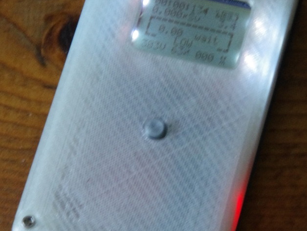
Case for uRADMonitor Kit 1 running on a Nokia battery
thingiverse
The uRADMonitor is a networked Geiger-Müller counter. More info here: http://www.uradmonitor.com/uradmonitor-kit1-1/. I got mine via the indiegogo campaign. I have a few extra Nokia batteries (the biggest being a BP-4L), so wanted to use one of those rather than a pair of AA's. It allows a nicely compact case design. But I haven't tested how long it will last on a full charge yet. I'm waiting for the charger I got on ebay first. Installing contacts for the battery is really fiddly. Also, the uRADMonitor cannot run from a voltage greater than 3.3V. So, I used a diode, both to cause a voltage drop of around 0.6V (to drop the 3.8V from the battery down to around 3.2-3.3V), and also because the legs of the diode make decent battery contacts for this type of Nokia battery. You only need to connect to the + and - terminals of the battery. There is no support for charging the battery, so you just have to remove it and use a desktop charger like the DT-33, or a phone which uses the same battery. My plan is to have the counter running at home from the 5V input most of the time; the battery is just for occasional outings to check radiation levels in other places. So, I tried to design the case with holes for diode legs to stick through, and end up in the right position to act as battery contacts. The plan was to bend them downwards and shove the ends into the second set of holes, to hold them in place. However the holes ended up a bit small, so I used the soldering iron to heat the diode legs so that they could melt their way through... which resulted in less-precise positioning than I hoped for. But close enough after some adjustment; and then I glued down the ends of the legs to the bottom of the battery compartment, very gingerly, with a small dab of epoxy. I used some epoxy to hold them in place on the inside of the case too, knowing that soldering to them would tend to let them move around again, what with PLA's melting temperature being so low. Then I (very quickly, to avoid melting the plastic too much) soldered a short length of fine stranded wire to the plain-wire contact, soldered that to the negative battery terminal on the board, and finally soldered the other end of the diode (mostly covered in tiny shrink tubing) to the positive battery terminal on the board. I'm not sure how well those makeshift battery contacts will hold up, but so far so good. It's possible to buy actual Nokia battery contacts on ebay, but they are surface-mount, so actually the thing to do is to design a little PCB which can hold the contacts in place, and in turn is designed to be a part of the 3D-printed case somehow. I didn't get that far yet. I used #4-40 machine bolts and nuts on the 3 corners that have through-holes on the PCB. The ethernet module is in the way, which is why there is not a hole on the 4th corner, I guess. Oh well, 3 bolts kindof hold the case together anyway. Two of the bolts pass quite close to the Geiger tube, so you'll have to bend the fuseholders (which are used as Geiger-tube-holders) over a little, so the tube sits right up against the side of the LCD. I wrapped that area of the tube with tape just in case there is some voltage on that part of the tube which is undesirable from the LCD's perspective. (And afterwards, check the bolts with your 400V-tolerant voltmeter to make sure they really aren't in contact.) The case is designed with this little mod in mind: there are struts to hold down the tube assuming you have pushed it over into that position. So all in all, it's quite a fiddly project; but if you got one of these kits, you need some kind of case for it. I've also added a wall mounting bracket which can attach to the side of my power-over-ethernet wall box http://www.thingiverse.com/thing:2085666, and can hold either this type of uRadMonitor kit, or a Model A2, or any other model which gets packaged into the same metal case (lozenge-shaped, 25x75 mm).
With this file you will be able to print Case for uRADMonitor Kit 1 running on a Nokia battery with your 3D printer. Click on the button and save the file on your computer to work, edit or customize your design. You can also find more 3D designs for printers on Case for uRADMonitor Kit 1 running on a Nokia battery.