 GrabCAD
Centrifugal pump
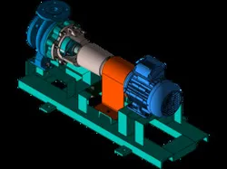
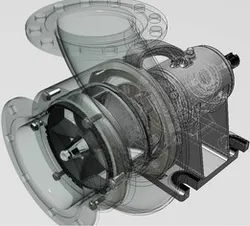
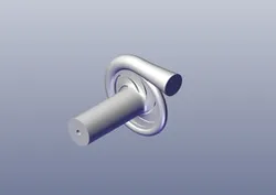
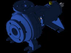
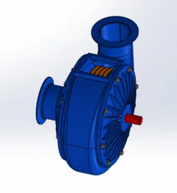
A centrifugal pump is a mechanical device used to transport fluids by converting rotational energy from a motor or engine into kinetic energy in the fluid. It is one of the most common types of pumps used in various industries and applications.
Here's a description of the main components and operation of a centrifugal pump:
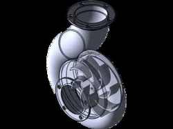
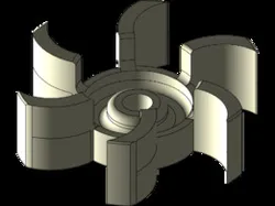
1. Impeller: The impeller is a rotating component inside the pump that consists of curved blades or vanes. It is responsible for imparting kinetic energy to the fluid by rapidly rotating and creating a centrifugal force. The impeller is typically made of metal alloys or composite materials.
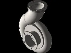
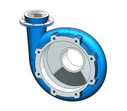
2. Casing: The impeller is housed within a stationary casing or volute. The casing is designed to guide the fluid flow and increase pressure by gradually expanding in diameter. It captures the fluid from the suction side and directs it towards the discharge side of the pump.
3. Suction and Discharge Ports: The pump has two main ports: the suction port and the discharge port. The suction port is where the fluid enters the pump, typically through a pipe or hose, while the discharge port is where the pressurized fluid exits the pump.
4. Shaft: The impeller is mounted on a shaft, which is connected to a motor or engine. The shaft transfers the rotational energy to the impeller, causing it to spin.
5. Seals: Centrifugal pumps are equipped with seals to prevent leakage of fluid along the rotating shaft. Common types of seals include mechanical seals or gland packing.
6. Bearings: Bearings support the rotating shaft and reduce friction. They help maintain the alignment of the rotating components and ensure smooth operation.
Operation:
1. Priming: Before starting the pump, it needs to be primed, which involves filling the casing and suction pipe with the fluid to create a continuous flow. This ensures that the pump is fully immersed and eliminates air or gas pockets.
2. Start-up: When the pump is activated, the motor or engine drives the shaft, causing the impeller to rotate. As the impeller spins, fluid is drawn into the pump through the suction port due to the centrifugal force created by the impeller's blades.
3. Fluid acceleration and pressure increase: The rotating impeller imparts kinetic energy to the fluid, causing it to accelerate radially outward. This acceleration converts into pressure energy as the fluid flows into the expanding casing. The pressure energy increases as the fluid moves from the suction side to the discharge side of the
Direct link to the original creator's page
Also Available On
More from Mohamed Samy
Similar Models
Model Specifications
Frequently Asked Questions
How do I download Centrifugal pump?
Click the "View on GrabCAD" button above to visit the original model page on GrabCAD. You can download the OTHER, SOLIDWORKS file directly from the creator's page for free.
What 3D printer can I use for this model?
This model is compatible with most FDM 3D printers (Creality Ender 3, Prusa MK3S+, Bambu Lab, etc.) and resin printers (Elegoo, Anycubic). Check the original page for recommended print settings and materials.
Is this 3D model free to download?
Yes, this model is available as a free download on GrabCAD. Some creators accept tips or donations.
Can I modify this file?
Check the license (see original page) on the original GrabCAD page. Most STL files can be modified using free software like Blender, TinkerCAD, or Meshmixer.