Chicken Door Automation for Omlet
prusaprinters
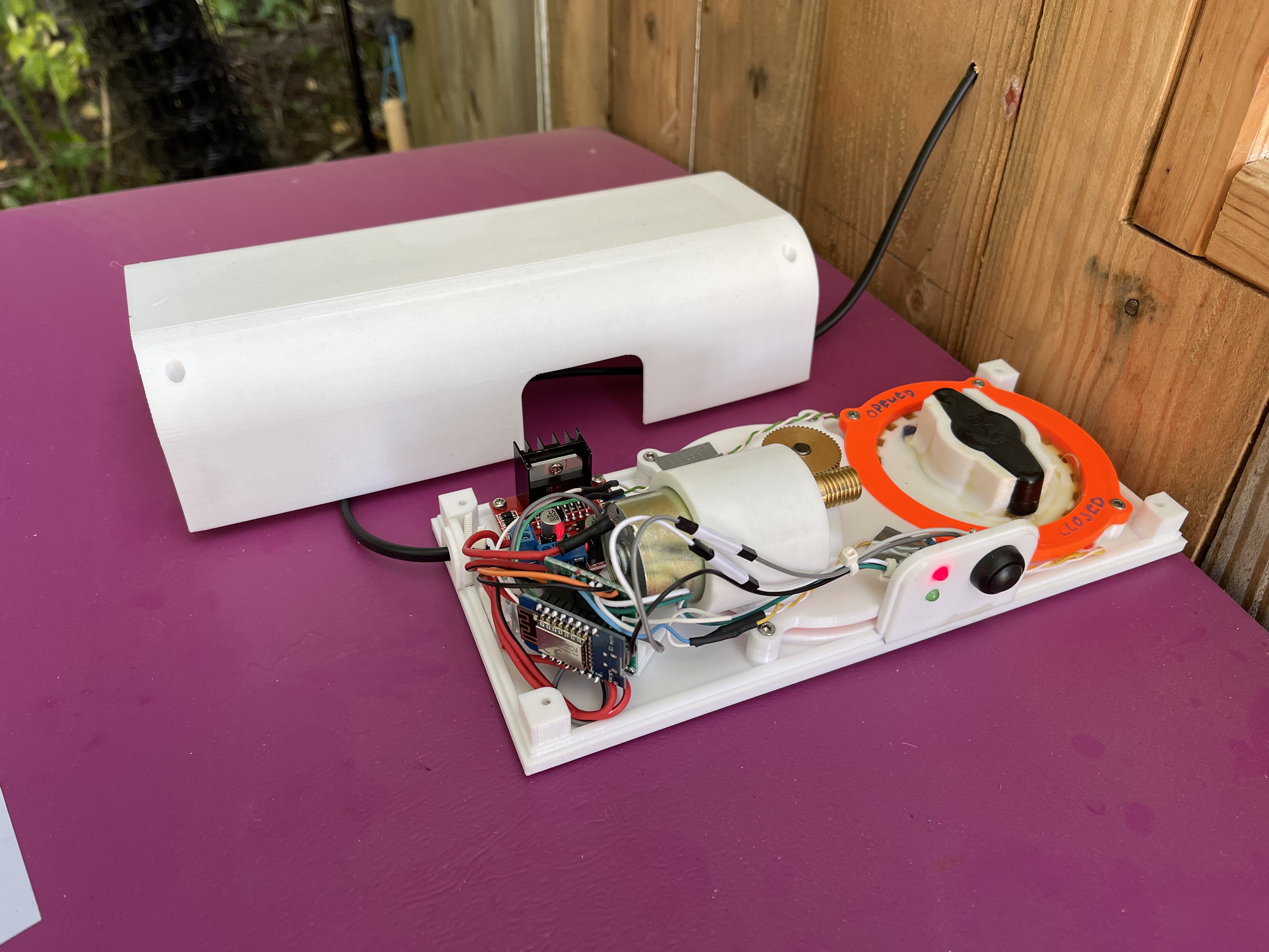
<p>This is a chicken door automation designed for our two Eglu Cube and one Eglu Go chicken houses. Operated by an ESP8266 microprocessor featuring a RESTless API, it can be easily integrated into a home automation system.</p><figure class="media"><oembed url="https://youtu.be/9xjhSOqxbWA"></oembed></figure><h3>Features:</h3><ul><li>can be added (almost) without modifying the chicken house</li><li>controls a motor to open / close the door</li><li>controls a light to attract chickens to move in</li><li>supports several commands using a RESTfull API:<ul><li>door status</li><li>open door</li><li>close door</li><li>light status</li><li>turn light on</li><li>turn light off</li></ul></li><li>button to open and close the door manually</li><li>displays door status using two LEDs</li></ul><h3>How we use it:</h3><p>Doors are opened automatically at sun rise or 7am - whatever comes last. Light is turned on at sun set. Door closing is operated from remote - but manually. This is because our chickens have not completed their learning curve to move in completely yet. To not wrap the chickens, we watch them using an IP cam and close it from remote by issuing a HTTP request (integrated into our home automation) . Once the door is closed, the light is turned off automatically.</p><h3>Possible improvements:</h3><ul><li>detect when a chicken is wrapped by the closing door and open it again</li><li>add gaskets</li><li>protect against self destruction</li></ul><h3>Printing:</h3><p>Use 0.4mm nozzle, 0.2mm layer height, and PETG filament. Most parts do not need support and can be printed using the model orientation. BaseTopMotor and the Lid need “support on built plate only”. MotorMount needs to be rotated by 90 degree on the closed end (the one with the screw holes). In addition, it needs “support on built plate only”.</p><h3>Parts required (see photo on red table):</h3><ul><li><a href="https://www.amazon.de/-/en/AZDelivery-D1-Mini-ESP8266-12F-Compatible/dp/B01N9RXGHY">ESP8266 D1 Mini</a></li><li>red and green LEDs, two matching resistors (330 Ohm)</li><li>button for manual operation (for 12mm hole)</li><li><a href="https://www.amazon.de/gp/product/B0824V7YGT">12 V DC gear motor</a></li><li>230V / 12V DC transformer</li><li><a href="https://www.amazon.de/gp/product/B07DK6Q8F9">Motor Drive Controller Board Module L298 N H Bridge DC</a></li><li><a href="https://www.amazon.de/gp/product/B07G5811RT">brass worm shaft set 6mm</a></li><li><a href="https://www.amazon.de/gp/product/B07PDZ9LDR">flange coupling 6mm</a></li><li>some 12V LED light (1W or smaller)</li><li>a custom 6mm stainless steel axle</li><li><a href="https://www.amazon.de/-/en/gp/product/B07Z4RR4QV">2 reed contacts, 1 matching magnet</a></li><li>the usual small electronic parts and cables</li><li>M3 screws at lengths 8mm, 10mm, 20mm</li><li>2 component glue of your choice</li></ul><h5>Building instructions:</h5><h5>Assemble Base</h5><ul><li>print all parts</li><li>glue MotorMount into BaseTopMotor</li><li>once dried, add a 20mm M3 screw to join the two parts even better</li><li>create stainless steel axle according to sketch and photos</li><li>push motor into mount and fix it using 6 M3 8mm screws</li><li>add worm to motor axis and tighten its screw</li><li>solder 2 reed contacts to thin cables, test functionality using a magnet</li><li>glue reeds and cables into Base</li><li>place the magnet into one(!) of ZahnradKnebel1 or ZahnradKnebel2, keep the other hole empty(!)</li><li>place flange coupling into ZahnradMotor and fix it using 3 M3 8mm screws</li><li>place ZahnradMotor into Base</li><li>push axle into flange and make sure it is aligned to Base's bottom,</li><li>tighten 2 screws in flange coupling</li><li>place motor with BaseTopMotor onto ZahnradMotor</li><li>fix it using 4 M3 10mm screws</li><li>make sure ZahnradMotor can turn freely, add 4 spacers otherwise</li><li>push worm gear on axis so the motor is connected to ZahnradMotor</li><li>connect ZahnradKnebel1 / ZahnradKnebel2 and place them into Base</li><li>place BaseTopKnebel on top of ZahnradKnebel1 / ZahnradKnebel2</li><li>fix it using 4 M3 10mm screws</li></ul><h5>Electronics</h5><p>Not detailed here. </p><p>See photos for the circuit diagram. Everything except the transformer will go into the base. So the power supply cable going into Base is 12V DC. In case you add a light (recommended), its cable is going through the remaining hole in the Base floor.</p><p>The ESP8266 program is provided on <a href="https://github.com/HarrysLapTimer/ChickenDoor">GitHub</a>. See instructions available there.</p><p>I recommend to use sockets for the ESP8266. This allows you to remove it and test / flash it at your desk instead of the chicken stable. ;-)</p><p>I have added two mounts for the ESP and the motor driver. They match the part I have used (see links above). You may need to design your own in case your choose different boards. Both mounts are added to the Base (see photos) using double-sided adhesive tape.</p><h5>Calibration and assembly to chicken house</h5><p><strong>Please read through this section carefully.</strong> The system can self-destruct itself in case you do not follow this instructions.</p><h5>Pre-testing</h5><ul><li>do not assemble with the twistable handle of the Eglu yet, initial calibration should be done on your desk!</li><li>with Base assembled, Electronics finished and ESP8266 flashed, connect to power</li><li>in case the magnet in ZahnradKnebel is positioned above the open or close reed contact, you will see one LED on and one off; in case the red one is on, the system in “door opened” position; in case the green one is on, the system is in “door closed” position</li><li>in case the magnet is somewhere else (not closing one of the reed contacts), both LEDs will blink, the motor will turn until ZahnradKnebel is in open position</li><li>in case the motor turns but doesn't stop, there is a problem with the open contact not being closed</li><li><strong>to make sure things work once the system is attached to the chicken house, press the button; this should make ZahnradKnebel move between close and open positions</strong></li><li>check motor polarity: opening the door needs to turn ZahnradKnebel counter clockwise (top down view), closing needs to turn clockwise; switch polarity in case it is the opposite</li><li><strong>finish by moving the system to “open door” position</strong></li></ul><h5>Real life testing</h5><ul><li>bring the system to your chicken house and re-check the turning of ZahnradKnebel and the Eglu's twistable handle is sound</li><li>remove the four screws of BaseTopKnebel and remove it</li><li>remove the ZahnradKnebel1 and ZahnradKnebel2 but memorize their exact position</li><li>place the base in the chicken house so you can pull up the twistable handle through the big hole</li><li>put grease into the housing of ZahnradKnebel1 and ZahnradKnebel2 - the handle will push these two down later; the grease helps to reduce friction</li><li><strong>make sure the twistable handle is in “open door” position</strong></li><li>pull the handle fully up and place ZahnradKnebel1 and ZahnradKnebel2 under the handle; depending on the factory side handle assembly, this can be difficult</li><li>let the handle go down so it sits between ZahnradKnebel1 and ZahnradKnebel</li><li>recheck everything</li><li>hold the base with a hand and turn on power; the red light should go on as the door is in open position</li><li>while still holding the base, press the button to check closing / opening the door</li><li>find the base position you have the least friction / noise</li><li>screw the base onto the chicken house using four screws going through the Base's floor</li><li>as the housing is rounded, it makes sense to add some spacers so the Base's floor is perpendicular to the door axle</li><li>re-test operation now that everything is fixed</li><li>connect and install the optional lightning by drilling a hole through the chicken house's roof (and through the remaining hole in the Base's floor</li></ul><h5>Calibration</h5><ul><li>both the open and close reed contacts will be triggered before the door is fully opened or closed</li><li>adjust CLOSE_RUNOVER_MILLIS and OPEN_RUNOVER_MILLIS in the sketch to add an amount of milliseconds the motor should continue to turn after the contact is closed already; in case the values are too high, things may break; in case the values are too low, the door will not open / close completely; start with zero for both and increase by 100ms between testing; our two devices have 500 to 800ms set;</li></ul><h5>Final tests</h5><ul><li>as the system can be remote controlled, try these REST APIs using a browser:<ul><li>http://<IP>/opendoor</li><li>http://<IP>/closedoor</li><li>http://<IP>/status</li><li>http://<IP>/illuminate</li><li>http://<IP>/illuminationoff</li><li>http://<IP>/statusillumination</li></ul></li></ul><p>Do not forget to put the lid on the system. Protect the system against rain.</p><p>Congratulations!</p>
With this file you will be able to print Chicken Door Automation for Omlet with your 3D printer. Click on the button and save the file on your computer to work, edit or customize your design. You can also find more 3D designs for printers on Chicken Door Automation for Omlet.