Classroom Spectrometer with Raspberry Pi - In Progress
prusaprinters
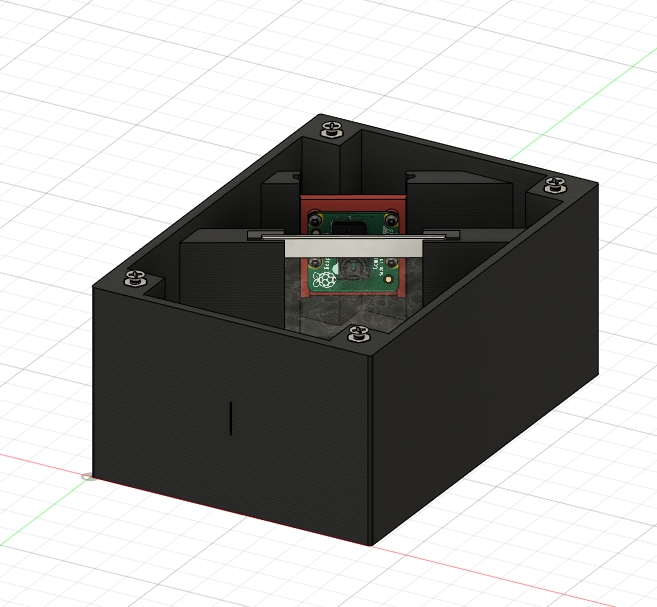
<p>About a year ago my brother, who is finishing his PHd in Physics, approached me about designing a housing for an affordable spectrometer for use in a classroom and that could be utilized for low grade lab use. It primarily utilized an NOIR Raspberry Pi Camera, a Raspberry Pi, and the affordable 500 lines/mm diffraction gratings which are commonly used in classrooms. He was inspired by the paper written by Yara Woo and Young-Gu Ju, "Fabrication of a high-resolution smartphone spectrometer for education using a 3D printer." (<a href="https://arxiv.org/abs/1805.05464">https://arxiv.org/abs/1805.05464</a>). The software which is being modified and utilized for this project can be found at: <a href="http://blog.durablescope.com/post/BuiltASpectrometer/">http://blog.durablescope.com/post/BuiltASpectrometer/</a> .</p> <p>We worked through several iterations of the housing design before finding one which met all of the characteristics that he was looking for in a housing. The prototypes were sent to him to begin testing and working out problems on the software end. In that time he had an undergraduate student working to complete the project who has since graduated and the project has come to a bit of a standstill. With his permission I'm publishing the files and as much information about the project as we have in hopes that the open source community can come together and bring this project to fruition. At the end of the day, this is a spectrometer with a large array of capabilities which should cost no more than US$80-100 to produce.</p> <p><strong>Notes on the housing:</strong><br/> The slit for light to pass through is 0.2mm wide and 26mm tall, excess light being allowed into the enclosure from other angles can be controlled through removable baffle immediately inside of the enclosure from the slit opening. The battle is held in place by a baffle lock, otherwise the baffle can slide out with the slightest handling of the housing. The angle from the slit opening to the diffraction grating is 30 degrees (+/- ~1 degree due to movement of the grating within the slot). The Pi Camera is placed so that lens is centered on the diffraction grating, with the camera module parallel to the grating. On the rendering, different colors denote parts which are printed separately. (note: the lid for the housing is not shown pictured in the renderings)</p> <p><strong>Assembly of Housing:</strong><br/> The lid of the housing is designed to be held in place with 4 - #4-40 screws. The housing does have locations where 4 - #4-40 hex nuts can be placed into the housing for extra security, these are slightly undersized and can be placed by heating the nuts with a soldering iron and moving them into place. In metric using countries, M3 screws should still work to hold the lid into place, however the cutout for the nut will be too large for an M3 nut, super glue or another agent will need to be used to hold it in place if this is desired.</p> <p>The screws holding the camera in place are a function of the Raspberry Pi camera, thus they are standard computer screws and sized for M2 screws. A #2-56 screw should still work in a pinch though.</p> <p><strong>Problems encountered to this point:</strong></p> <ol> <li><p>in tests it has been found that the walls of the housing can allow in light in the IR spectrum, this has been mitigated to a point by wrapping the housing in aluminum tape. Testing has not been done to see if it can be mitigated through increasing all thickness within the print parameters. These problems were specifically found with PLA printed enclosures, it was not tested with other materials.</p> </li> <li><p>Focusing the camera for the correct focal length to maximize the size of the diffraction pattern gathered has been a problem, thus maximizing the resolution of the spectrometer. Though there have only been limited attempts to mitigate this problem.</p> </li> <li><p>Maximizing the software library being utilized. The lack of flexibility in the software made making any modifications difficult to tackle, and made acquiring the maximum amount of information from the device challenging.</p> </li> </ol> <p><strong>Continuing Progress:</strong><br/> If there are people out there who are able to work on this project and make progress, please share it with the community. At this time neither my brother nor I have the time to dedicate the time to tackling the problems faced by this project, though if we are able to work on it in the future we will be sure to post updates in the hopes that this can be utilized in a classroom setting sooner rather than later.</p> <p><em>This project was done in partnership with the University of New Hampshire Physics Department. Special credit to Mr. Anthony J. Rogers, Dr. Elena Long, and Mr. Jordan Loll for their work and expertise on this project.</em></p> <h3>Print instructions</h3><p>I have printed this in both PLA and PETG, we haven't seen much different between printing in Black or a medium tone purple. I would not recommend printing in white, yellow, or any highly reflective color.</p> <p><strong>Layer Height</strong><br/> 0.2mm</p> <p><strong>Infill</strong><br/> 20%</p> <p><strong>Perimeters</strong><br/> 2</p>
With this file you will be able to print Classroom Spectrometer with Raspberry Pi - In Progress with your 3D printer. Click on the button and save the file on your computer to work, edit or customize your design. You can also find more 3D designs for printers on Classroom Spectrometer with Raspberry Pi - In Progress.