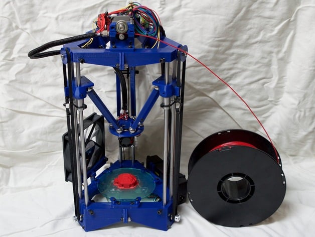
CloverPlus v2 Delta 3D Printer
thingiverse
It appears that this text is an update log for a project, likely related to 3D printing or robotics. Here are some key points mentioned in the log: **Power Supply Mount** * A new power supply mount design has been posted (cloverplus_ps_mount.stl) * It attaches to one of the outside bottom 5mm frame mounts and uses 2 4mm zipties to secure a 58mm wide x 132mm long power supply * The top and bottom frame pieces have been updated to move the wire guide zip-tie holes 3mm out to clear the power supply mount **Carriage Bearing Clamp** * The carriage bearing clamp holes have been narrowed slightly to better grip M4 x 6mm grub screws **Arm Design** * A new arm design has been posted, along with an STL file for a 11.4mm long arm * The design uses 2 supposed 6mm x 6mm cylinder magnets **Controller Mounts** * A ramps controller mount .stl has been added and the controller mount .scad source has been updated * Controller mounts have also been added for the v2 frame for Azteeg X5 v1.1 and v2.0, and Osoyoo mksbase 1.3 **Effector and Hotend Mount** * The effector and hotend mount have been redesigned in OpenSCAD to resolve dimensional accuracy issues and improve maintainability * New STL files for the effector and hotend mount have been added (cloverplus_effector_v2.stl, cloverplus_hotend_mount_v2_e3d.stl) **Top and Bottom Frame Pieces** * Updated top and bottom frame piece STLs (cloverplus_top_v2.stl, cloverplus_bottom_v2.stl) with improved design * Requires 12 additional M5 x 16mm screws to clamp the rods in from the sides **Miscellaneous** * A fan mount bracket has been added for 100mm fans with 91mm spacing * The BOM has been updated throughout the log
With this file you will be able to print CloverPlus v2 Delta 3D Printer with your 3D printer. Click on the button and save the file on your computer to work, edit or customize your design. You can also find more 3D designs for printers on CloverPlus v2 Delta 3D Printer.