CNC 3018 Pro Z-Axis Upgrade
thingiverse
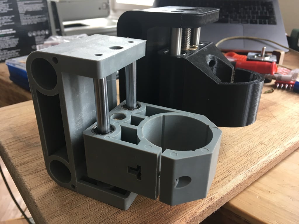
### WARNING I just printed the model with LM16UU bearings and noticed the carriage does not fit with the default "side plates", so I made my own (out of aluminum). The flex that those 16mm bars have is still quite a bit, so I guess if you really want a sturdy machine you might have a better time using completely different linear guides. I will add a LM12UU and LM14UU variant for the X linear guides soon. ### UPDATE I recreated the model using the (free) OpenSCAD (http://www.openscad.org) modeler. This new model incorporates some improvements that I felt were necessary after printing the original design that I made in Fusion 360. - I used LM16UU bearings for the X-Axis, a lot of play is actually coming from the 10mm standard bending under pressure. - I deepened the T8 nut holes so the carriages can move over the connector between the stepper motor and the spindles, increasing the range of the X and Z axis a bit. - I added a "cage" for mounting an anti-backlash T8 spindle on the Y axis as well. - It is now written in OpenSCAD, so changing parameters should work better than before. I re-exported the STL files from the OpenSCAD file and made a LM10UU and LM16UU version for the X carriage, and a LM8UU and LM10UU version for the Z carriage. ### CNC 3018 (Pro) Z AXIS UPGRADE I wanted a more sturdy Z-Axis for the 3018 Pro so I designed a better one. The main problems with the original design are the cheap LM8UU and LM10UU bearings and bad quality T8 spindles, I also found the 2x 10mm linear guides for the X axis will bend easily, all of this together gives the machine a lot of play by default, making cutting harder materials very slow. I printed the parts on my Ender 3, but had to make the holes in the design a bit bigger to make all parts fit correctly, so **WATCH OUT**, the STL's that are uploaded have +0.5mm on the vertical holes and +0.4mm on the horizontal ones! If you can print your holes perfect, go set the VerticalHoleDiameterAdjust and HorizontalHoleDiameterAdjust "variables" / "parameters" to 0 in the OpenSCAD drawing and export new STL files. I used PLA with 20% infill and a 2.5mm wall thickness. I designed the Spindle mount separate from the Z Carriage so it can be replaced with other kinds of mounts. ### PARTS NEEDED **These parts are needed for all variants of this modification** - 8x Screw to fasten the spindle nut, I used pretty small wood screws. - 6x Screws to fasten the spindle mount to the z carriage (sorry, didn't measure the length, see drawing for now) - 1x skateboard bearing (will have to measure it / provide the exact type here soon) ### Parts for LM16UU linear guides X axis upgrade (recommended) **These parts are ONLY needed if you want to upgrade the X axis linear guides to 16mm bars** - 2x 16mm rod with a length of 360mm - 4x LM16UU bearings - 1x T8 Anti-backlash spindle 400mm ### Parts for LM10UU linear guides X axis upgrade **These parts are needed if you only want to upgrade the X axis's bearings and spindle** - 4x LM10UU bearings - 1x T8 Anti-backlash spindle 400mm ### Parts for LM10UU linear guides Z axis upgrade **These parts are ONLY needed if you want to upgrade the Z axis linear guides to 10mm bars** - 2x rod with a diameter of 10mm and cut to length (123mm) - 8x LM10UU note that I doubled the amount of bearings in the Z Carriage - 1x T8 Anti-backlash spindle 123mm ### Parts for LM8UU linear guides Z axis upgrade **These parts are needed if you only want to upgrade the Z axis's bearings and spindle** - 8x LM8UU note that I doubled the amount of bearings in the Z Carriage - 1x T8 Anti-backlash spindle 123mm Happy to answer any questions!
With this file you will be able to print CNC 3018 Pro Z-Axis Upgrade with your 3D printer. Click on the button and save the file on your computer to work, edit or customize your design. You can also find more 3D designs for printers on CNC 3018 Pro Z-Axis Upgrade.