CNC-Egg(Plotter Ro)Bot Design with Modular T-Slot Base
prusaprinters
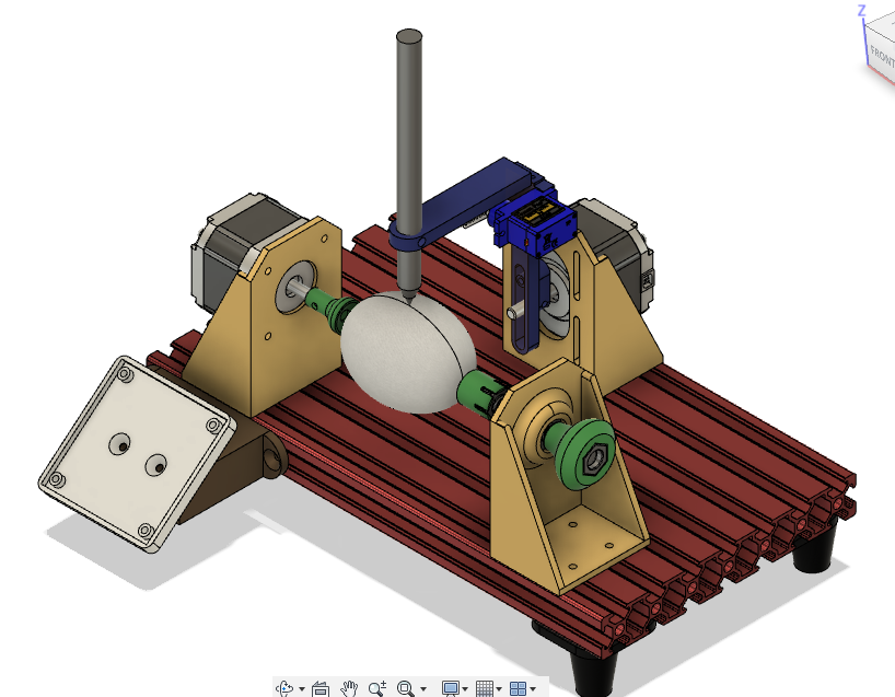
<p>I have long been enamored with the idea of blowing the minds of my nieces, nephews, and in-laws with robot produced Easter Eggs from an EggBot-type device.</p> <p>Opportunity to make one of these semi-spheroid plotting devices from scratch fell into my lap when I adopted a nearly dead Mendle-style cartesian 3D printer. I took a look at the charred printer board, thought to myself that I don't like electrical fires, and stripped it for parts.</p> <p>After reading about EBs for a while to gather an understanding of parts are needed and what features are handy/useful for adjusting the mechanics of the drawing operation, I set out to design one completely from scratch.</p> <p>I did this for many reasons:<br/> -First, because I didn't find any existing designs on Thingiverse with ALL of the features I personallly wanted<br/> -Secondly, my collection of parts was somewhat non-standard<br/> -Most importantly, I want to and it seemed like a fun challenge to re-invent a wheel.</p> <p>If you have some of the same raw parts, I encourage you to use this, make it your own, and have fun printing/plotting.</p> <h3>Print instructions</h3><h3>Category: Robotics How I Designed This</h3> <p><strong>Bill of Materials - Hardware</strong></p> <p>This project was designed based off a number of material constraints based on the parts I had on hand. to build my exact version of this project you will need:</p> <p>-2x NEMA17 stepper motors<br/> -1x SG90 9g Micro-Servo<br/> -1x 680ZZ bearing<br/> -1x M6 Theaded Rod + 2x M6 Nut<br/> -1x Spring<br/> -1x EiBotBoard+Power Supply<br/> -1x Computer with Inkscape software with EggBot plug-ins<br/> AND<br/> -1x flat chunk of an HDPE Milk Jug<br/> -1x spong and some sandpaper</p> <p>A large handful of M3 hardware including socket-head machine screws, some countersink machine screws, and M3 nuts (if using the captive nut t-slot nuts). I will post the right quantity of these items once I've had a chance to print this out and put it together. If you have an M3 thread tap, most of the M3 nuts can be omitted.</p> <p><strong>Bill of Materials - Printed Parts</strong></p> <p>This item was designed to be very modular using an 8020-derived aluminium extrusion profile. As such, most parts affix to the base extrusion using M3 hardware and t-slot nuts. For this project you will need to print:</p> <p>-1x Axial NEMA17 motor mount bracket<br/> -1x Radial NEMA17 motor mount bracket<br/> -1x Pen Arm Motor Horn<br/> -1x Pen Arm Upright<br/> -1x Pen Arm<br/> -1x Spring Coupler mount bracket<br/> -1x Pull Knob<br/> -1x Driver-Side Egg Cup<br/> -1x Spring-Side Egg Cup<br/> -4x Extrusion Legs<br/> -1x EiBotBoard Mount<br/> -1x EiBotBoard Bracket<br/> AND<br/> -1x 8020 Aluminium Extrusion derivative (8 slots)</p> <p>Many T-slot nuts. These are provided in both single and double (20mm hole spacing) versions, as well as both captive nut and to-be-tapped versions. An accurate count will be provided once I've built it.</p> <p><strong>Design of Pen Arm and Radial Motor Mount</strong></p> <p>There are numerous design features in this portion of assembly to allow for adjustment of positioning of the radial arm mechanism.</p> <p>The motor mount itself can be moved in the x and y directions for alignment of the long-axis of the pen with respect to the "center" of the sphere/egg. This is done to accommodate different sizes of spheres/oviods.</p> <p>Additionally, the radius of the pen arm can be lengthened or shortened by adjusting it relative to the pen arm horn that is attached to the motor axel, Again, for different sized spheres or oviods.</p> <p>Lastly, the motor itself can be positioned lower in the motor mount to offset the center of the radius relative to the central spin axis of the sphere/egg on the other CNC-controlled DOF. The effect this has is to "flatten" out the curve of the pen tip as it traverses the surface of the egg. For a perfectly spherical object such as a baseball or ping-pong ball, the motor should be mounted in it's highest position. For an egg, it is recommended that the motor be moved to roughly the mid mount position in the vertical slots in the motor mount.</p> <p>The pen arm hinge is intended to be a piece of HDPE from a milk jug, with holes drilled to align with the holes on the Pen Arm and the Pen Arm Upright.</p> <p>All screw holes and the grub screw holes should be tapped.</p> <p><strong>Assembly</strong></p> <p>Using T-Slot nuts and M3 hardware, affix legs and motor mount printed parts to the base as shown in the exploded view of the assembly.</p> <p>Install both NEMA17 motors to motor mounts.</p> <p>Assemble Pen Arm Sub-Assembly with hinge and SG90 servo and install sub-assembly on Radial Motor Axle.</p> <p>Assemble Spring Coupler Sub-Assembly on the Spring Coupler Mount.</p> <p>Attach Egg Cups to both sides of the Axial DOF. These egg cups should have a piece of sponge glued to their cup end. A small amount of sand, sandpaper, or other grit material should be adhered to the free sponge end to provide grip on the egg/sphere.</p> <p>Attach EBB mount assembly to the extrusion base as per the exploded view.</p> <p>Wire up the NEMA 17 motors and the servo to the EBB prior to installing in the mount. Affix the EBB to the EBB mount plate.</p> <p><strong>Use</strong></p> <p>Search the internet for EggBot software and use instructions. I'd tell you more, but this is not the focus of this Thing and I am definitely not an expert. Good Luck!</p>
With this file you will be able to print CNC-Egg(Plotter Ro)Bot Design with Modular T-Slot Base with your 3D printer. Click on the button and save the file on your computer to work, edit or customize your design. You can also find more 3D designs for printers on CNC-Egg(Plotter Ro)Bot Design with Modular T-Slot Base.