CNC Foam Cutter Carriages
thingiverse
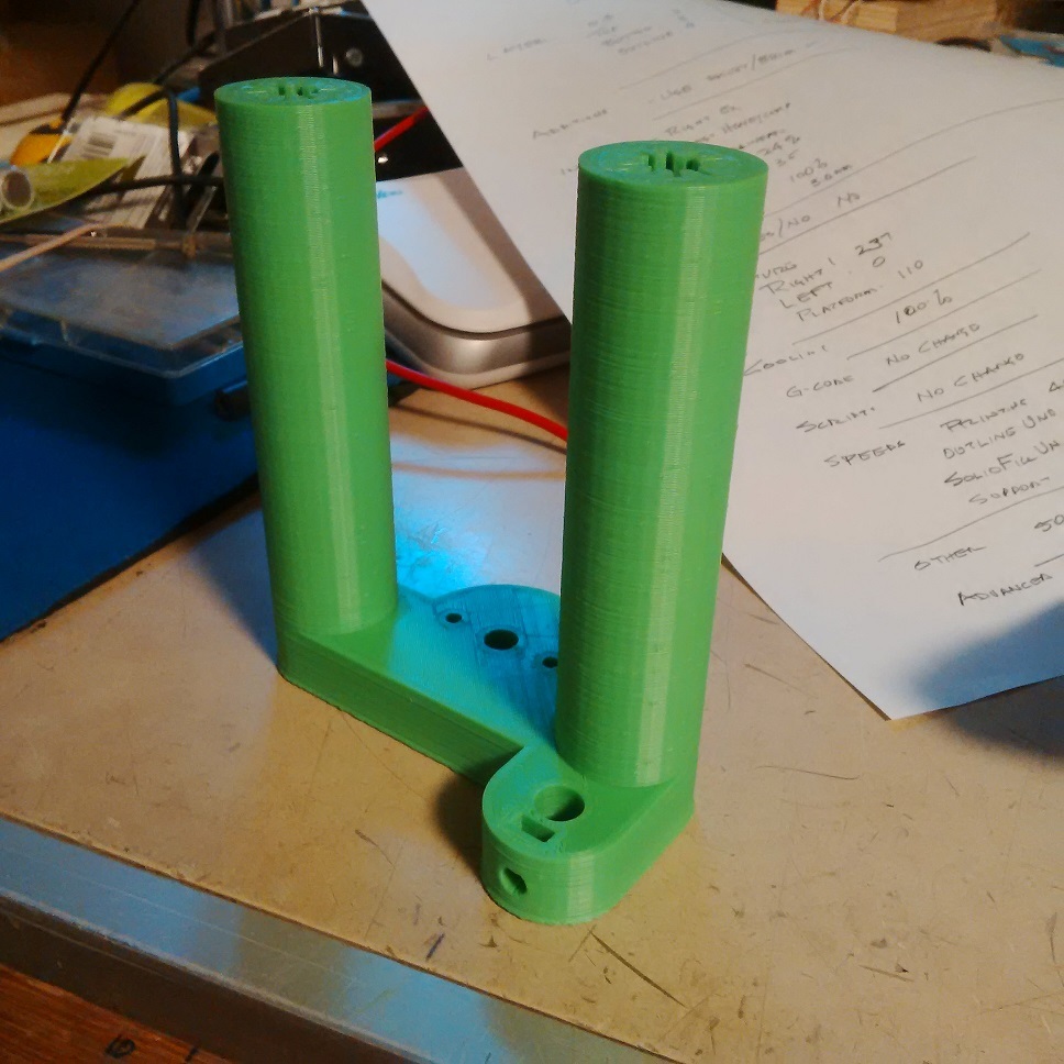
This is a remix. The guide rods on the CNC foam cutter are 70mm apart. The original carriages are 50mm long on the vertical Axis and 60mm long on the horizontal Axis. The bearings are printed full length inside. When trying to make the carriages slide easily, you may have to ream them to fit the variations in your rod, or the variation in the tuning of your printer. This can cause the bearings to become a bit curved along the length. UPDATE 20-January-2021 To speed up printing, the part has been changed. See the 2 new files for the Horizontal carriages. The hole down the center no longer has ridges. The smooth walls mean the shells or perimeters print much faster. Also there are two versions with different diameters of the hole through the bearing surface. When you have finished printing, the part should slide freely on the guide rods. Tuning a 3D printer to get the bearing diameter correct is difficult. So to test the fit I have the following suggestion. Turn the part upside down in your slicer. That is put the long bearing tubes pointing down. Slice the part. Start printing. When 15-20 mm of the length has been printed, CANCEL the print. Now test the printed bearing surface on your guide rod. If the 0.500 size fits and slides WITHOUT filing or sanding, you are in luck. Reslice the part the correct way around and print it. If the piece of the bearing is tight and won't slide on, or is hard to push, then repeat the above process but use the file labelled 0.520. The difference is the bearing inside diameter is 0.020" larger or about half a millimeter. If this does not slide end to end on your guide rod easily, then your print setting are way off. Note: Due to the squishing of the first layer or 2 it is usually necessary to file the last 1 or 2 mm of the bearing to allow it to slide on the guide rod. So do the filing first and then try the samples. The bearings need to slide very easily on the guide rods. If not, the carriages can jump as the bearing play in the stepper motors gets compressed and released. In other words, an oversize bearing may be better than a bearing that is tight. You should be able to place the small test piece of bearing made in the above process on the guide rod. Then tip the guide rod down and up. The test piece should slide freely from end to end when you tip the rod back and forth. Because your are using 2 guide rods, a slightly slack fit bearing is better than a too tight fit. This would be less of an issue if there was a thrust bearing arrangement for the lead screw. A thrust bearing would make sure there is no end play in the lead screw movement. Then the printed bearing could be a bit tight without affecting the finished foam cut. Since then I have modified the horizontal parts. The end away from the stepper motor now has a thrust bearing installed and the lead screw has no end play. UPDATE ENDS By being so short they are also easier to rock and jam a bit until the force from the lead screw causes the carriage to jump. This affects the finish of the foam cuts. Bearing makers like Igus recommend that the length of a carriage be 1.5 to 2 times the distance between the guide rods.The original carriages are less than 1 times this distance. These new ones have 2 changes. First the carriages are 110mm long. This makes them meet the 1.5 times the 70mm spacing of guide rods. ( 70x1.5=105 ) Second, the bearing surface is only the last 20mm of each end of the carriages. This reduces the contact area. Less contact area reduces the friction. Also it is easier to ream out the short length of bearing surface to fit the guide rods. Think of a car having only 4 contact points at the tires. The wheel base is longer than the track of the wheels. This is what we have achieved with this change. The pictures show the vertical carriage, the horizontal carriage, and the summary screen of my Makerbot Replicator 2x after the job completed. It really did take a bit less than 11 hours to print the horizontal carriage. A friend with Solidworks skills redrew the parts. His name is Corey Smith of SolutionSmith Engineering Limited, of Nova Scotia. I owe him a great deal of thanks for his time and his patience dealing with me. Thanks Corey.
With this file you will be able to print CNC Foam Cutter Carriages with your 3D printer. Click on the button and save the file on your computer to work, edit or customize your design. You can also find more 3D designs for printers on CNC Foam Cutter Carriages.