Colorimeter V0.0
thingiverse
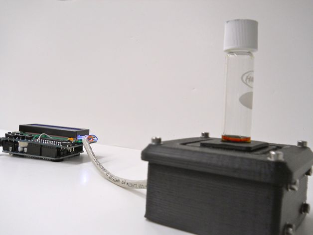
Build your own colorimeter by following this open-source project found at http://www.appropedia.org/Open-source_colorimeter. The current firmware only reports absorbance and transmittance; a calibration protocol is in development. The STLs provided will help you build a case for the colorimeter, as well as the required electronics. This device can determine high range Chemical Oxygen Demand (COD) by measuring absorbance at 606 nm, which is an absorbance peak for the chromic ion. The cuvette holder is designed for Hach COD digestion vials. The light source was chosen specifically for chromic ion determination and can be altered to measure other ions. This project is part of a larger initiative at Michigan Tech to reduce the cost of scientific equipment using open-source hardware. For more information, read this article: http://mtu.academia.edu/JoshuaPearce/Papers/1935580/Building_Research_Equipment_with_Free_Open-Source_Hardware. You can also find more open-source research tools at http://www.thingiverse.com/jpearce/collections/open-source-scientific-tools. To build the colorimeter, you'll need an Arduino Uno, an Adafruit LCD shield, an LED with peak around 606 nm, a suitable resistor for your chosen LED, a TSL230R light-to-frequency sensor, a proto board, conductors (Cat 5 cable works great), black ABS or PLA filament, 12 M3 screws, 12 M3 nuts, and 20 M3 washers. Assemble the parts, solder the components to their respective boards, fit the boards into the case, download and install the firmware on the Arduino, attach the LCD shield, power the device, align the LED and sensor, remove the cuvette holder, attach the cover to the case, and finally calibrate the device using the forthcoming protocol.
With this file you will be able to print Colorimeter V0.0 with your 3D printer. Click on the button and save the file on your computer to work, edit or customize your design. You can also find more 3D designs for printers on Colorimeter V0.0.