Component Tester
thingiverse
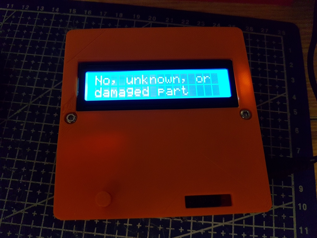
I have observed numerous instances of component testers with ZIF sockets located on the front, however my model is distinct (featuring a screw terminal socket instead). There are advantages and disadvantages to the screw terminal compared to the ZIF socket, likely boiling down to personal preference. I designed a case for this specific model and do not believe one exists yet. Print both components with the outside face lying flat on the bed. I printed each part individually. The base can be printed without supports if your printer excels at bridging, but I used supports as a precaution. No supports are required for the lid. A brim was used due to the large surface area, preventing the edges from curling up. During my initial print, I wasn't paying attention to the first layer and inadvertently created a slight blemish near the screw hole where some filament got caught on the hot end while heating up; however, previous iterations printed flawlessly. Once printed, remove the screws from the bottom of the PCB, place the unit in the base, and secure it using M3X10 bolts (button head hex). The top screws can then be removed from the LCD tester and the printed lid with button inserted into the hole. Place the plunger end inside the case and screw it down into the standoffs using M3X10 bolts. If you plan to install a battery first, consider adding foam on the inside to prevent rattling. I found battery power unreliable when using the tester, so I opted for the power jack instead. Change Log: After printing the model shown in the pictures, I slightly thickened the screw supports in the lid due to thin walls. The power jack hole was elongated after realizing my jack was mounted on the board at an angle. The top screw access hole was shifted slightly towards the top. If any issues arise, feel free to reach out and I will advise. 20/08/2019 I replaced my component tester with a similar model featuring TH components instead of SM components. Upon inspection, I noticed differences in the button length and added a longer STL file for compatibility. The new button required a spring (not necessary but a nice touch) to prevent flapping. To accommodate the power jack port, an exacto knife was used to elongate it further, as reprinting the box wasn't deemed necessary. Check out my YouTube channel DonLabs for basic electronics tutorials and tips. My video on multi-meter use features the component tester and also includes a tutorial on utilizing the screw terminal socket effectively. https://youtu.be/6aWe66QK5N0 https://youtu.be/uasB_2nvYtA
With this file you will be able to print Component Tester with your 3D printer. Click on the button and save the file on your computer to work, edit or customize your design. You can also find more 3D designs for printers on Component Tester.