Compound Gears and Gear Ratio Elevator
thingiverse
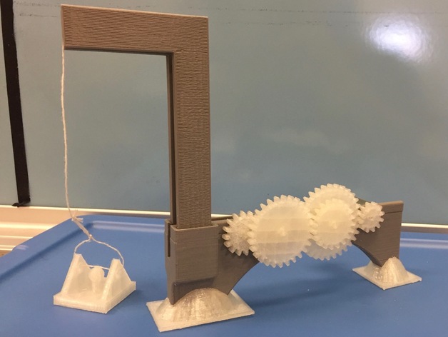
This is a remix of the Elevator of Terror from the #DCMakerBotMakeathon. The lesson plan from the Elevator of Terror is really cool, but the files were lacking, so I've created a set of files to support using the lesson plan that was created by TechEdSloth. Using this project, you can create a #ScienceProject or #EngineeringProject that will help your students learn about gear ratios, compound gears, mechanical advantage and trade offs between power and speed. Students are tasked with creating a compound gear that can control the speed of an elevator in this model. They can use TinkerCAD to place the bore holes for their axles in the Base - allowing for appropriate placement of the gears in their gear train. I have provided a series of gears of varying sizes and also provide a link for creating your own gears using a Gear Generator Tool that I adapted from John Wolter's Spur Involute Gear. The difference is that my Gear Generator Tool already has the holes for the axles of a 2mm drive shaft and the 4mm driven hex shafts. To try to reduce binding caused by flashing from the printing process, I also added fillets to the driven gears in the file, but not on the STLs themselves. You could probably accomplish the same by just lightly sanding the sides of the gears before construction. Print Settings Printer Brand: MakerBot Printer: MakerBot Replicator (5th Generation) Rafts: Doesn't Matter Supports: Yes Notes: I provided the demo base with and without Mesh Mixer supports. If you use the "MM" version, you don't need to use supports, because they are already there for you. If you have students design the gear train and bore the holes for the axles, you'll want to use #MeshMixer to create an easily removable support system. The base will take about 5 hours to print. Axles and Pulleys don't take long at all, the gears vary from 20 minutes to an hour, depending on the size. All the files you need are in the zip file. The ones that are outside of the zip file are in there as well, but I included copies so you could see some of them in the preview. Post-Printing Putting it together All of the axles have a central hole through which you can fasten the string for the elevator. For people with fat fingers (like mine) feed the string through the bearing hole for the axle, then tie it off on the outside. You'll have to pull the string as you put the axle through the bearing hole, but it will fit. Placing the pulleys Place the pulleys on the pegs on the left and right frame pieces before snapping them together and inserting into the slots on the base. There is one pulley that is smaller than the other two, it goes on the short peg. Make sure you thread the string through the pulleys before you attach it to the elevator. Adding the gears Clean off the excess flashing from the printing process and lightly sand the edges to eliminate interference points. Use a sharp knife to eliminate flashing internal to the hex hub of the gears (don't be too aggressive, it still needs to be a hexagonal shape in order to work on the axle). When assembling your gear train, remember to avoid interaction between gears that aren't supposed to mesh. Once you've verified fit and finish, glue the gears to the axles. How I Designed This Tools I made the base and the axles using #OnShape. The left and right frame pieces and the pulleys were brought over from the project I remixed, they were made using #TinkerCAD, as was the elevator. I used TinkerCAD to bore the holes in the base and to make the feet for the base to sit in. Making gears I have provided a series of gears of varying sizes and also provide a link for creating your own gears using a Gear Generator Tool that I adapted from John Wolter's Spur Involute Gear. If you go in to OnShape to create your own gears, the following guidelines apply: This model does best with a pitch of 16. It does not like going below 12 teeth, so remember to keep your smallest tooth size at 12 or greater. When you modify these gears, you need to change the number of teeth in the parametric constraints and in Sketch 1, where it says "__x" as the number closest to the center of the circle. Now, if part of your gears don't show up when you change the number of teeth, you need to update the selections Extrude 1. Select all the missing teeth and they'll show up in your model. Important parts for the OnShape edit if you want to design your own gears To Create Your Own Base Edit the Base, not the demo base Import the Base.STL into TinkerCAD and place holes for the axles where you have calculated that they should be spaced to allow for the gears that you are using. To best fit the axles, the holes should be 6.5 mm in diameter. I've included an engraved line on the STL to help with your alignment of the holes for the axles and the motor. To print the Demonstration Base The demonstration base was made for a motor that has a 10 mm collar (which snuggly fits in the motor hole) like one of these, but, I didn't use that one specifically. Just make sure you have a 10 mm collar on the motor to fit into the hole provided. If you don't, use TinkerCad to fill in and then replace with a hole of the correct size. To print and assemble the demonstration model, you will need the following parts: One (1) elevator.stl One (1) Base-Demo.stl (or Base-DemoMM.stl) One (1) Axle Single.stl Two (2) Axle Compound.stl One (1) Driver - 12 Teeth.stl One (1) Driven - 12 Teeth.stl (to pair with the 28 teeth on the same compound shaft) One (1) Driven - 16 Teeth.stl (to go by itself on the single shaft) One (1) Driven - 20 Teeth.stl (to pair with the 32 teeth on the same compound shaft) One (1) Driven - 28 Teeth.stl (to pair with the 12 teeth on the same compound shaft) One (1) Driven - 32 Teeth.stl (to pair with the 20 teeth on the same compound shaft) One (1) set of Feet.stl One (1) set of Pulleys.stl One (1) Left.stl (for the left support) One (1) Right.stl (for the right support) You'll also need some wire or alligator clips. I was able to run my motor with 2 C batteries. When assembled, your compound gear train looks like this. The 16 tooth gear meshes with the 12 tooth gear that is on the same axle as the 28 tooth one. The 28 tooth gear meshes with the 20 tooth gear that is on the same axle as the 32 toothed one. The 32 tooth gear meshes with the 12 tooth driver gear, which is mounted on the shaft of the motor.
With this file you will be able to print Compound Gears and Gear Ratio Elevator with your 3D printer. Click on the button and save the file on your computer to work, edit or customize your design. You can also find more 3D designs for printers on Compound Gears and Gear Ratio Elevator.