Concentric Rings O'Clock
myminifactory
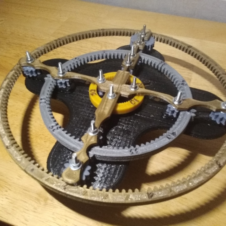
This is my contribution for this great contest ! #MechanicalClock3D @MyMiniFactory Finding the real good idea for a particular watch was not easy but as soon as it occurred to me, I immediately started to draw it. It too me a long time (about 50 hours, during 3 weeks), but I loved doing this project ;-) I had the idea of concentric rings, small ones for seconds, the second for minutes and the last for hours. On the screenshot of the design under Fusion360 section, we can better understand the design of the different gears: it was imagined a V-nesting system, reversing it to each stage of toothed wheels, so that the different gears force each other and can not escape!! The working is very simple, the clock must be hung on the wall. It's based on a very easy to find NEMA17 step by step motor, with an arduino Nano and an A4988 Driver PCB. The motor must have an impulsion for only one step by second, the mechanical system allows the clock run and indicate the time ! Please click on the picture with the ZOOM + TOOL for watching the whole frame ... wire all the composants SKETCH ARDUINO (you must flash the Arduino nano with your computer with the Arduino IDE) - Code to upload on the chip : _____________________________________________________________________________________________________ // Drive Stepper motor using A4988 stepper motor driver// for more info visit iknowvations.in // first define the pinsconst int DirPin = 4; // this pin defines direction CW or CCWconst int StepPin = 5; // pulse this pin to move one stepconst int SPR = 200; // Steps per revolution void setup() { // Make pins as Outputs pinMode(StepPin, OUTPUT); pinMode(DirPin, OUTPUT);}void loop(){ // First let us rotate shaft clockwise digitalWrite(DirPin, HIGH); // defines the direction to clockwise // Pulse the step pin for(int x = 0; x { digitalWrite(StepPin, HIGH); delayMicroseconds(1000); digitalWrite(StepPin, LOW); delayMicroseconds(1000); } delay(1000); // Short delay of one second // Now rotate shaft counterclockwise digitalWrite(DirPin, LOW); // Again pulse the step pin for(int x = 0; x { digitalWrite(StepPin, HIGH); delayMicroseconds(1000); digitalWrite(StepPin, LOW); delayMicroseconds(1000); } delay(1000); // Short delay of one second } _____________________________________________________________________________________________________ ASSEMBLY INSTRUCTIONS : Please, see the .pdf document on the 3D files to upload or on the attached files on the right side below the description (+a screenshot of the 6 pages on the scrollable banneer :-) You must choice what you prefer for the final look of this clock : you can choose to finish with the "cross" part, or the mix of the two pieces with the "optionnal-face" part. You could either choose wich ring you want for your Clock between the "Hours Ring" or "minutes-ring-v2-plays-on-hours-ring-move-move-it-each-5-minutes", for customize the move of your clock ! Try the 2 options ... All the conception is optimized on a 3D printer with 0.4mm nozzle with 0.2mm layers high. The design has been thinked to be printed on a "classic" 3D printer like the PRUSA with a 200mm by 200mm bed. For those with a larger 3D printer, you can use the "FULL Hours Ring" file (you need a 250mm X 250mm tray) You have to assembly the 4 parts of the Hours Ring : it has been concepted for using a little filament segment (1.75 mm of diameter) to glue thru the 4 parts when assembled (perhaps you must adjust the 8 holes with a drill). Sometimes, if it's the good diameter glue is optionnal, this assembly sytem is very strong You need a set of small screws : 2X BTR / 10mm long / 3mm diameter ------- for the NEMA17 motor 29X Washers / 3mm hole 13X conic head screws / 25 mm long / 3mm diameter (I used 3Omm long screws, sorry, I had'nt the good lenght) 14X 3mm hexa nuts (One for the GT2 2O teeth pulley insert, for tighten it on the NEMA motor) [+13X 3mm hexa nuts, if you use you "cross" and the "optionnal-face" parts] 13X 3mm nylon brake nuts (to get close to the 3D room called "cross" without tightening it too tightly) 1X 3mm needle screw / 5mm long ( " " " " " " " " " " " " " " " " idem " " " " " " " " " " " " " " " " )
With this file you will be able to print Concentric Rings O'Clock with your 3D printer. Click on the button and save the file on your computer to work, edit or customize your design. You can also find more 3D designs for printers on Concentric Rings O'Clock.