Conductive ink – pen plotter style 3D printer upgrade
thingiverse
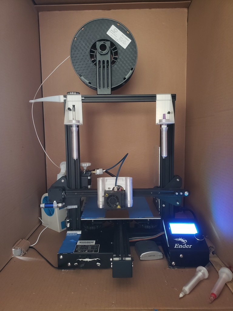
Conductive ink – pen plotter style 3D printer upgrade These add on printed parts and modifications will allow you to use your Creality Ender 3 Pro as a pen plotter, or if using conductive ink, a 3D PCB creator. The pen tools are non-powered and controlled by their position and gravity so no updated controller board is required. The parts are, A pen holder with twin heads, this is to hold the pen boot when printing. It has a left and right pen cradle to hold the pen boot when not in use, and several two part pen boots, each meant to hold a different type of pen, such as circuit scribe, buddy paint, and sharpie styles. The pen holder is held in place by two of the screws provided to hold the metal fan and hot end cover, this part should sit flush against the top of the metal tabs, and snug against left face of the cover, leaving a gap between the part and the right side fan. This part is designed not to interfere with the left side end stop switch, the pen holder left and right caps screw on the bottom tubes and are used for alignment. The left and right pen cradles are used to hold the pen when not in use, these slide into the top cross beam front slots and rest on the upright columns, it is critical that these parts sit parallel to the columns, a small bit of tape can be used underneath them to align the pen holder opening with cradle slot opening. The pen boots have different configurations depending on the style of pen used. The circuit scribe pen top raps around the body of the pen and screws into the threaded shaft. The buddy paint is more of a bolt style, with a threaded shaft, and closed top cap. The sharpie is like the other bolt style only it has a tapered inside opening smaller at the top, to better fit the body shape of the marker. a small bit of tape can be used to make the pens fit snugly inside the boot. Alignment and motion of the pen tip can be controlled by adjusting the pen boot end cap, and the pen holder cap up and down the length of the threads. once the pen bottom distance is set where the pen tip is one layer step below the extruder nozzle height the pen boot end cap can be used to adjust the pen boot resting place within the holder, the fixed distance between the top tapered cone and the bottom tapered cone on the shaft can be used to adjust the tilt or pivot point when drawing out the segments, lowering the holder cap allows the pen to pivot on the upper cone, raising it allows the pen to pivot on the bottom boot cone. This allows you to adjust for the best pen position between the tolerance of the shaft size and the inside hole diameter of the pen holder. To add the use of these holders and tools to your program, add the following code segments to your data or as part of your extruder set up, Manually step through the locations before proceeding automatically to verify correct locations, you may need to adjust these x y and z values once you have assembled the parts. You will need to include the loading segment at the beginning and unload segment at the end of your data for the desired tool. ; left pen load G28 ; Home all axes needed once at the start of file to establish coordinate system zero G1 Z20.0 F3000 ; Move Z Axis up little for extruder clearance when heating G92 E0 ; Reset Extruder G1 F600 E-7.5 ;retract filament G1 F1200 X30 Z60 ; move pen holder under cradle G1 F600 Z170 ; move to pick up pen G1 F500 Z175 ; move to clear cradle push G1 X80 ; move picked up pen to clear cradle G1 Z60 ; move down to clear cradle ; end of left pen load ;left pen unload G1 F1200 Z60 ; clear part G92 E0 ; Reset Extruder G1 F300 E7 ; put filament back in place G1 F1200 X80 ; move pen to clear cradle location G1 F600 Z175 ; move pen up to cradle height G1 X30 ; move carriage to cradle drop position G1 Z60 ; move to drop off pen ; end of left pen unload ; right pen load G28 ; Home all axes needed once at the start of file to establish coordinate system zero G1 Z20.0 F3000 ; Move Z Axis up little for extruder clearance when heating G92 E0 ; Reset Extruder G1 F600 E-7.5 ;retract filament G1 F1200 X202 Z60 ; move pen holder under cradle G1 F600 Z170 ; move to pick up pen G1 F500 Z175 ; move to clear cradle push G1 X152 ; move picked up pen to clear cradle G1 Z60 ; move down to clear cradle ; end of right pen load ; right pen unload G1 F1200 Z60 ; clear part G92 E0 ; Reset Extruder G1 F300 E7 ; put filament back in place G1 F1200 X152 ; move pen to clear cradle location G1 F600 Z175 ; move pen up to cradle height G1 X202 ; move carriage to cradle drop position G1 Z60 ; move to drop off pen ; end of right pen unload Included in this package of data are examples of a simple circuit as reference to one way to prepare the needed files, the ".doc" files are Gerber(RS274X) data for reference. one additional note to add, when using circuit scribe conductive ink pens it is advisable to prepare your work in advance, my finding is the ink will write on plastic well, but that the drawing time of each pen once opened is about 11 hours, after that although some ink is still in the tube, the ink comes out slower and inconsistently, and only works when the environment is about 70 degrees or above.
With this file you will be able to print Conductive ink – pen plotter style 3D printer upgrade with your 3D printer. Click on the button and save the file on your computer to work, edit or customize your design. You can also find more 3D designs for printers on Conductive ink – pen plotter style 3D printer upgrade.