Conic Sections- Full Cone
thingiverse
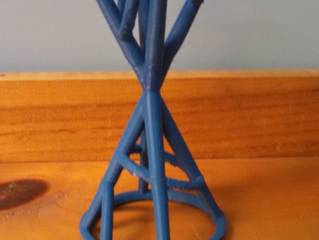
The 3-inch model showcases the conic sections in mathematics on a three-dimensional scale. Conic sections originate from two cones stacked on top of each other, tip to tip, being cut by planes in a three-dimensional space, resulting in two-dimensional graphs. By utilizing this model, mathematicians and students can visualize the origin of these conic shapes more clearly and manipulate them with ease. The use of conic sections in classrooms aligns with the Maine mathematics standards dictated by the Common Core Mathematics Standards. Specifically, standards CCSS.MATH.CONTENT.HSG.GPE.A.1, 2, and 3 emphasize graphically representing and working with conic sections through equations. However, understanding the conceptual ideas behind conic sections and their relation to cones is often challenging. Even when students are provided with a set of equations and instructions on how to work with them, it does not facilitate an understanding of how these shapes relate to cones. By incorporating this model into classrooms, students can witness firsthand where planes cut through cones to generate the various two-dimensional shapes from a three-dimensional perspective. A. Reynolds - MAT 363, December 2014 Print Settings: Printer Brand: SeeMeCNC Printer: Rostock MAX Rafts: No Supports: No Notes: The model has a tendency to detach from the printing bed when printing. To prevent this issue, use hairspray or tape to secure the bed and maintain a hot temperature. Taping down the base circle after it prints is also advisable. Design Process: This model was created using Rhinoceros (Rhino) software. Initially, two cones were constructed with their tops intersecting at the point of the apex. Subsequently, planes were used to cut through the model at specific angles to generate two-dimensional graphical representations. The parabola was sliced at a slanted vertical angle, hitting only one cone. The hyperbola was cut at a similar slanted vertical angle, striking both cones. The ellipse resulted from cutting one cone at a slanted horizontal angle. The circle and point were created by constructing the two cones together, where slicing one cone at a straight horizontal line produced the circle, and the point represented the intersection of the two cones. The final conic section, the line, presented an initial challenge in the design process. Lines were generated by creating a skeleton of the two cones and then removing them. Once the ellipse, hyperbola, and parabola were created, the intersection of the planes and cones was defined in Rhino. The planes were subsequently removed, leaving only the curves produced by the slicing planes. The cones themselves were deleted from the model, resulting in "floating" curves that were created. Four lines were then constructed from the two circles left from the cones, forming a skeleton of a cone. This model incorporated all necessary components for conic sections and was theoretically printable. To add thickness to the model, piping was applied to facilitate 3D printing. (A.R., Dec. 2014) Custom Section: Mathematical Questions/Challenges: When the model failed to print, it became apparent that the printer was attempting to print on a point of singularity. The middle point, technically speaking, is a single point on the entire plane. Even after adding width to the piping, which increased the surface area, there were still two issues to address. The first concern was determining how large to make the intersection so it could support the top half of the cones. When we increased the pipe width, the surface area increased, potentially solving the problem of thinness in the model. However, when we increased the piping to boost the surface area, the weight from the top half of the model also increased. This created a new issue where the weight was still too great for the increased surface area to support. As we attempted to increase the surface area, the weight continued to rise, exacerbating the problem. We then considered how to increase the surface area between the two cones without increasing the weight as well. The angle between the two cones also influenced the surface area, with wider cross-sections at greater angles potentially balancing out the weight and pressure issues. However, when attempting to print, the model was still deemed too thin in multiple areas. We discovered that Rhino uses a multiple radius piping method, which tapers the pipe so it is smaller on one end. Implementing this new variable helped decrease the weight on the top of the model, potentially leading to a larger print size in future attempts.
With this file you will be able to print Conic Sections- Full Cone with your 3D printer. Click on the button and save the file on your computer to work, edit or customize your design. You can also find more 3D designs for printers on Conic Sections- Full Cone.