Connect Four - Given up :-)
thingiverse
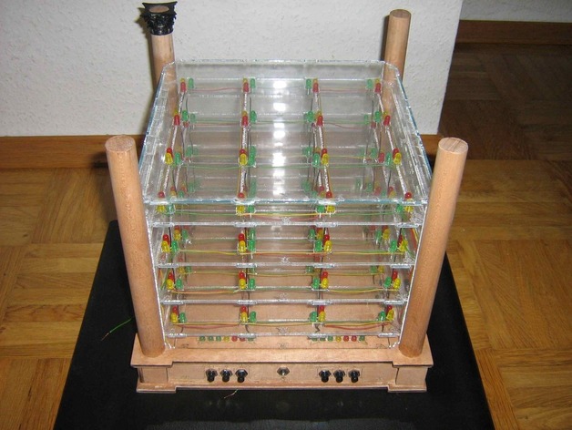
"Connect Four," a game with better gameplay potential than TicTacToe, could be improved using integrated circuits as multiplexers to light up bigger matrices. This allows for a four-win scenario on a larger 4x4 matrix. By modifying the Arduino cube example, a "Connect Four" game can be created with a 4x4x3 setup, featuring three LEDs per game field for players using red, green, and yellow colors (allowing up to six players). Two 4-to-16 multiplexers can be used to add status displays at the bottom like high scores, game options, player count, winning combinations, gravity settings, and a timeout feature. The player controller features three buttons for x-, y-, and z-axis movements, which are color-mapped for improved player experience. These colors are also displayed in the game field's intersection points to indicate active game fields. The fourth button can accept or move the game field along the axes. The buttons have different series resistors and are connected to the Arduino's analog input for readout. A small update notes that the player controller was eventually reduced to a PCB, then replaced by integrated buttons on the side and top of the game field. The brain of the game was also replaced by the Big_Mainboard_A, produced with a PCB mill in the fablab, which was later updated to the B-version. Initial attempts used an analog readout for each button, but this proved too slow. In the second attempt, multiplexed LEDs were utilized to accelerate readout and simplify logic. However, these LEDs were only 1/16 as bright as normal ones, so using intelligent LEDs with two serial ports per RGB led would be more efficient. The project is currently a blinking cube that collects dust due to further improvements needed. The parts are cut and engraved with a laser cutter in various materials: acrylic glass, leather, and wood. Acrylic glass pages are populated with LEDs and connected by wire, while wooden parts are glued together using 2cm-diameter wood shafts as columns. Engraved wooden parts serve as sidewalls, top and bottom covers, and are decorated with Corinth capitals (3D-printed). The controller should be made using rounded rectangles for buttons and leather engravings. However, a PCB version was later used instead of the controller for each player, and buttons were integrated into the game field's sides for simplicity. A shield file contains a drawing for an Arduino shield with additional 3-to-8 ICs for the controller triggering, although this is still a work in progress. The latest version (Mainboard_B) features integrated buttons on the sides, connected to multiplexer/drivers and evaluated through a single input pin. Both multiplexers are steered in parallel for efficient gameplay.
With this file you will be able to print Connect Four - Given up :-) with your 3D printer. Click on the button and save the file on your computer to work, edit or customize your design. You can also find more 3D designs for printers on Connect Four - Given up :-).