Control MOSFET module directly from Arduino output pin
thingiverse
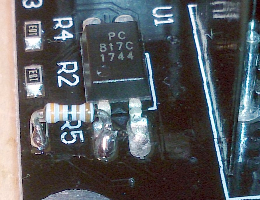
Human: How to Modify the MOSFET Module (http://s.click.aliexpress.com/e/I2FMBU7) to Control from a 5V Digital Output?\r\nTo control the module from a 5V digital output, you need to adjust the R5 value from 10k ohm to approximately 2.5k ohm.\r\nI added an additional 3.3k ohm resistor in parallel with R5.\r\n\r\nParts:\r\nMOSFET Module: http://s.click.aliexpress.com/e/I2FMBU7\r\nResistor, 3.3k Ohm (possibly 2.7 or 3.9 k ohm)\r\nPillar Washer M3*15 for MOSFET Board Support\r\n\r\nWhy?\r\nThe input of the MOSFET module must be connected to a RAMPS (or another 3D printer motherboard) power output.\r\nIt's no problem on simple configurations, but if you want to control additional controllers or fans, or two extruders, fan, and hot bed, you'll need four or more power outputs.\r\nRAMPS have many free digital outputs, but MOSFET boards require 12V (above 8V) in the control input to switch on.\r\nThe MOSFET module uses a photocoupler PC817 (http://akizukidenshi.com/download/PC817C.pdf - loses about 1.2V) to isolate the input and output circuits, as well as rectifiers (diode bridge, lose about 1.2V) to ignore the polarity of the input.\r\nAt the end, 5V from a digital output is too small to control the optocoupler through a 10k resistor.\r\nTo obtain sufficient current for the optocoupler, you need to modify the R5 value.\r\nThe modified MOSFET module works with 5V inputs and it's safe to control it with 12V inputs.
With this file you will be able to print Control MOSFET module directly from Arduino output pin with your 3D printer. Click on the button and save the file on your computer to work, edit or customize your design. You can also find more 3D designs for printers on Control MOSFET module directly from Arduino output pin.