Converter Step/Dir to RC PWM
thingiverse
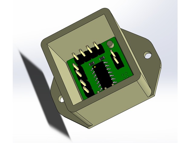
In one of my latest projects for creating a clone of AxiDraw, I utilized Arduino Uno GRBL (GRBL set to CoreXY) to drive the machine. When it comes to driving the Z axis, servo motors are the best choice – they are lightweight and fast compared to steppers. Unfortunately, GRBL has no PWM output to control the Z axis so I decided to make a small project to convert the STEP and DIRECTION signals to proper PWM for servos. There are some similar step/direction converters projects over the net but I needed some more features like: Homing of the head on power up End sensor for detecting when the head reached the home position Store the servo homing position into EEPROM and make the initial PWM to jump to this point Learning procedure – tell the servo where is the min and max allowed positions (restrict the servo to work in some area) and store the limits into EEPROM More precise PWM timing which relies on hardware timers After the work was done, I'm sharing the whole project – including the C sources and the HEX which are tested on real board and show excellent performance. Also added the PCB schematic, routing and Gerbers – ready to prototype it. Add a small plastic box which is 3D printed and will cover the PCB. The learning procedure for PWM limit works but in short it is: If during power up the CAL_ENDS jumper was closed (held to GND) the firmware enters learning procedure The head moves the middle position (1.5ms pulse) and starts moving toward one of the ends (the direction of the first movement depends on the status of DIR_HOME jumper) When the rotor hits the home sensors (HOME to GND) the processor records the moment PWM as the first limit and also as home position (after power on the motor will go to this position). You can use just a single button to imitate the HOME sensor. Once end detected on step 3 the motor reverses direction and goes until it hits the HOME sensor (you can use just a single button to imitate the HOME sensor). When HOME asserted the controller records the moment PWM value as the second limit. The normal operation of the controller is: After power up, it will move the head to last stored home position (from Step 3) The CNC sends step and direction signals which change the PWM and servo will move in the desired direction. One step from CNC will change the PWM pulse width with 1uS – the timings are done by hardware and is very precise. The period of the servo is 16ms, the PWM can change from 750uS to 2500uS During the CNC homing, the main CNC controller may want to initiate homing on Z axis – moving Z toward the end sensors until head hits the sensors. If there are no mounted end sensors and the controller hits the PWM limits it will assert the HOME line low just like there is an end sensor and will release it one the limit is not violated. Some characteristics: PWM period – 16ms 1uS per step Active on positive edge on STEP STEP speeds above 100KHz are acceptable Programmable upper/bottom PWM limits through learning procedure Detects end switches on HOME input When PWM is outside the PWM limits it asserts low the HOME input (imitation of end switches), when PWM goes back in limits – HOME pin will be released. I'll add later some more information – stay tuned.
With this file you will be able to print Converter Step/Dir to RC PWM with your 3D printer. Click on the button and save the file on your computer to work, edit or customize your design. You can also find more 3D designs for printers on Converter Step/Dir to RC PWM.