CR-10 Ultimate Z-Box: The ideal drag chain + X-axis stepper damper bracket + wire management solution
thingiverse
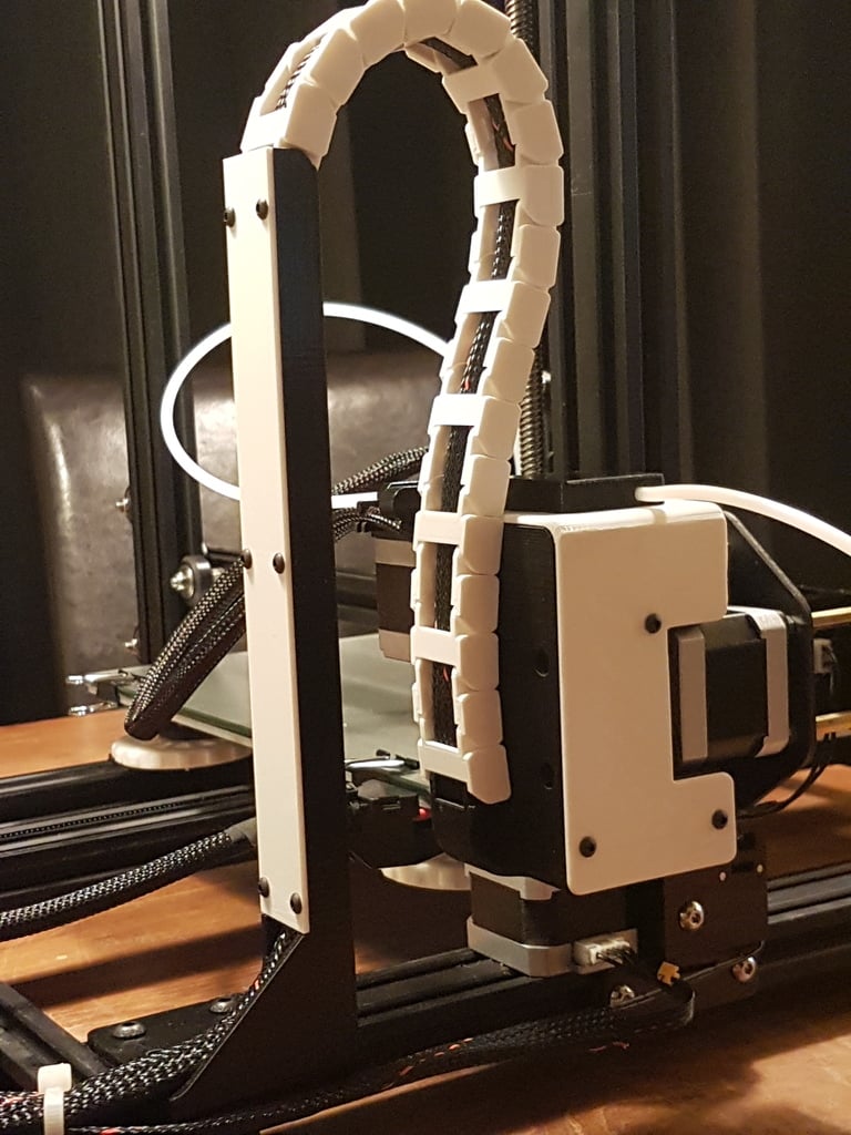
The text provided appears to be instructions for modifying or upgrading a 3D printer, specifically a CR-10 model. The modifications seem to focus on wire management, hotend connection terminal, and adding a filament sensor. Here's a breakdown of the instructions: **Wire Management** 1. Use braided sleeving around wires in the dragchain. 2. Place all wires in the Z box in the correct position, cutting the hotend cable if necessary. 3. Snap A and B type links together around the cable starting at the Z-box housing's integrated drag chain link. 4. Connect the last link bottom bracket. **Hotend Connection Terminal** 1. Cut the PCB to a size of 50mm x 25mm (adjusting the width slightly). 2. Solder two rows of 8 connectors on the back and front sides, respectively. 3. Use solder to connect the terminals together as shown in photos. 4. Place the PCB in the housing, adjusting if necessary. 5. Mark connections with a sticker or marker pen. 6. Connect wires from the drag chain to the back side of the terminal block. 7. Connect hotend wires (thermistor, fan) to the front side of the terminal block. **Hotend LED** 1. Cut pins on the LED to 10mm. 2. Solder a resistor (600 ohms is suggested) to one pin and connect wires to the other pin. 3. Use isolation material to cover bare conductors. 4. Connect the LED to the back of the screw terminal block on the hotend wire. 5. Push the LED into its designated hole, using glue if necessary. **Filament Sensor** 1. Route the wire/cable from the drag chain behind the terminal block. 2. Route it through a square hole in the Z-box cover and then through a hole in the filament sensor and underneath bridge. 3. Solder wires to the Normally Open pin and common terminal on the sensor. 4. Mount the sensor using 4 M4x8 screws on the Z-box cover. 5. Place PTFE tubing in both sides of the sensor (use caution with small tubing). Key points: * Use braided sleeving for wire management. * Cut hotend cable if necessary. * Connect A and B type links around the cable starting at the Z-box housing's integrated drag chain link. * Solder terminals together as shown in photos. * Connect wires from the drag chain to the back side of the terminal block, and hotend wires to the front side. * Add a filament sensor by routing the wire/cable correctly and soldering it to the sensor. Note: This text does not provide information on how to implement the sensor output on your CR-10.
With this file you will be able to print CR-10 Ultimate Z-Box: The ideal drag chain + X-axis stepper damper bracket + wire management solution with your 3D printer. Click on the button and save the file on your computer to work, edit or customize your design. You can also find more 3D designs for printers on CR-10 Ultimate Z-Box: The ideal drag chain + X-axis stepper damper bracket + wire management solution.