CR-30 BMG NF Crazy Direct Drive Mod (with 11% more build height -> 190 mm, volcano characteristics)
thingiverse
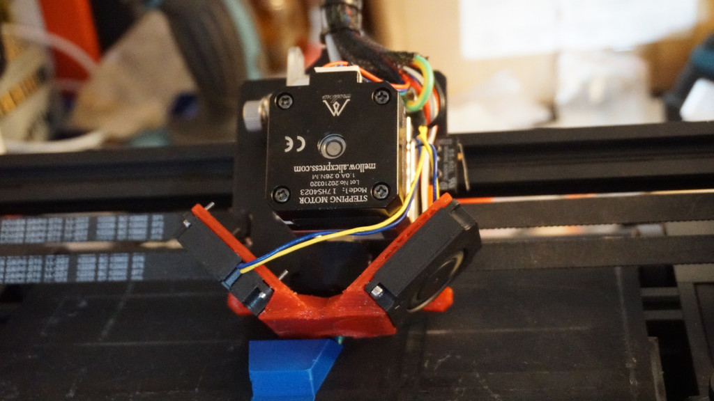
This thing includes instructions and printable parts for a direct drive conversion for the CR-30 based on the BMG NF Crazy. Pros considering the stock config: - 190 instead of 170 mm height - higher possible flow rate - pros dedicated to a direct drive in general Cons: - Costs about 60 - 80 $ - Higher moving mass (though I did not found issues using printing speeds of 100 - 200 mm/s and with current accels up to 3000 mm/s²) - Modding requires quite some efforts You need the BMG NF Crazy feeder: https://de.aliexpress.com/item/1005002347516347.html?spm=a2g0o.productlist.0.0.60777195B32eso&algo_pvid=2918a658-b9e0-4bc0-a52e-4af28bde3f3f&algo_exp_id=2918a658-b9e0-4bc0-a52e-4af28bde3f3f-18 ... an nf-crazy heatbreak: https://de.aliexpress.com/item/1005002508277058.html?spm=a2g0o.productlist.0.0.5f9f476e1ReUg7&algo_pvid=14839898-fd6b-4322-9cac-36883b47db62&algo_exp_id=14839898-fd6b-4322-9cac-36883b47db62-28 ... a suitable heaterblock: https://de.aliexpress.com/item/4001256975938.html?spm=a2g0o.productlist.0.0.5f9f476e1ReUg7&algo_pvid=14839898-fd6b-4322-9cac-36883b47db62&algo_exp_id=14839898-fd6b-4322-9cac-36883b47db62-27 ... a silicone sock for the heater block: https://de.aliexpress.com/item/1005002483572860.html?spm=a2g0o.productlist.0.0.5f9f476e1ReUg7&algo_pvid=14839898-fd6b-4322-9cac-36883b47db62&algo_exp_id=14839898-fd6b-4322-9cac-36883b47db62-32 ... a volcano nozzle with an accordingly shaped cone to fit the CR-30 printing angle, ideally made out of copper, brass is ok too, steel nozzles may cool down to quickly: https://de.aliexpress.com/item/32965490598.html?spm=a2g0s.9042311.0.0.27ae4c4d9k6XtO ... a 40 mm fan of your choice, ideally 24V, and some M2, M3 and M5 screws. You also need skills in 3D printing with PA or another heat resistant material and you need to drill a few holes into the mounting plate according to the printable stencil of this thing. When talking about front and back, the front is the side of the hotend mounting plate you look onto when viewing from the direction of the top aluminium extrusion to the hotend of the printer. Modifying the mounting plate (drilling 6 holes, if that is not an option read about an alternative mounting solution at the bottom): 1. Print the two stencils (nf_crazy_feeder_stencil and nf_crazy_cold-end_stencil). 2. In the meantime, remove the stock hotend, the endstop and everything so you end up with a bare mounting plate. The rollers and belts can stay attached. 3. Take the stencil and place it on the plate so that the longest bevel is up left and it flushes to the two protruded mounting holes of the stock hotend at the bottom of the stencil. Then slide it to the left against the lens head of the screw from the bottom left roller. That is the correct mounting position. Now mark the bottom two holes of the stencil on the plate and drill them through with a 3,5 mm drillbit. 4. Get your BMG NF Crazy feeder and check if it fits to the position. You have to drill another hole to fix it which is not included in the stencil: The aluminium body of the feeder has a hole at the top to fix the PTFE fitting. This hole will also be used as a mounting hole, drill a hole in the mounting plate accordingly (also 3,5 mm bore). 5. The fourth hole is a 12 mm one which acts as an air vent to cool the cold-end of the NF Crazy extruder. Its position can be determined using the lens heads of the roller screws and the reading "front" on the stencil. 6. For the last two holes there is no stencil: They are dedicated for the endstop which now has to be fixed on the plate according to the pictures and as near as possible to the aluminium body of the feeder. I did bend its soldering pins to achieve that, placed it by hand, marked the bores, drilled them with a 1.5 mm drill bit and threaded the holes with a 2 mm thread cutter. Alternatively to threading you can use nuts on the other side. Printing: - nf_crazy_part_cooling_fan_holde -> needs to be printed out of a heat resistant material, beyond the capabilities of ABS. I used PA (Nylon), however PMMA, PA or others might also work. One could also try one of those heat resistant PLAs (after annealing/crystallization), yet they may deform due to the thin walls during annealing. - nf_crazy_cable_holder, filament_sensor_holder, nf_crazy_fan_duct -> can all be printed out of standard PETG, ABS or similar. Would not recommend PLA despite for the filament_sensor_holder as the hotend/feeder/mounting plate gets warm. Assembly: 1. Assemble the BMG NF Crazy feeder and the hotend using the ordered volcano nozzle. Ideally you have some high temp silicone paste at hand to isolate the nozzle thread sticking out of the heater block (see the picture where I used a drill to get a smooth silicone coating). 2. Mount the assembled feeder/hotend to the mounting plate using some M3 screws - I guess I used 40mm ones for the bottom holes and a 6 mm one for the top one, but better have some screws at hand also for the following steps. 3. Mount the heater cartridge and the thermocouple (the stock ones do fit). 4. Lengthen the cable for the extruder stepper motor and attach the cable to the motor. My motor did have the same pin layout as the stock one so I did not have to switch pins in the plug - but you may need to do that. Check for the phases first to be on the safe side. 5. Now mount the nf_crazy_part_cooling_fan_holde using 2 M3 screws (10 mm or so). 6. After that you can mount the stock part cooling fans onto the holder you just installed, the stock screws should fit. 7. Mount the nf_crazy_fan-duct. Use either short screws (5 - 6 mm) or longer ones (16 mm) at the top as the nf_crazy_cable_holder will be mounted on the front with the same holes. Add a 40mm fan, ideally a 24v one so you can just replace it with the stock one. I used a 5V Noctua fan I had lying around. 8. Now mount the nf_crazy_cable_holder, make a nice cable arrangement using zip-ties. 9. The last step is mounting the filament sensor using the filament_sensor_holder. You need one of the stock PTFE fittings and 2 M5 screws (25 mm?) for that. Connect your new DD to the sensor unit using a PTFE tube, the stock one should work just fine. Finished! Now calibrate your E-steps and you are good to go! I can also recommend the CR-30 UART mod and the fan mod to make use of Linear Advance and silence. The difference with LA can be seen in the printing picture from the side (bulges disappear). I may update this in future for a better cold-end cooling solution, despite the given one being unconventionally neat it may be less complicated to cool the hotend from the left side. Alternative mounting solution: Another aproach would be mounting the BMG NF Crazy feeder/hotend just like it was designed to: Using the two bores (13 mm distance) which do fit the unmodified mounting plate. No drilling needed then, yet I noticed less rigidity, a little less printing space due to the motor being too far on the right, which also generates the need to mod the x-endstop combination using something to make trigger the endstop before the motor crashes into the x-axis fixture.
With this file you will be able to print CR-30 BMG NF Crazy Direct Drive Mod (with 11% more build height -> 190 mm, volcano characteristics) with your 3D printer. Click on the button and save the file on your computer to work, edit or customize your design. You can also find more 3D designs for printers on CR-30 BMG NF Crazy Direct Drive Mod (with 11% more build height -> 190 mm, volcano characteristics).