CR-30 Y-Axis Linear Rail Mod
cults3d
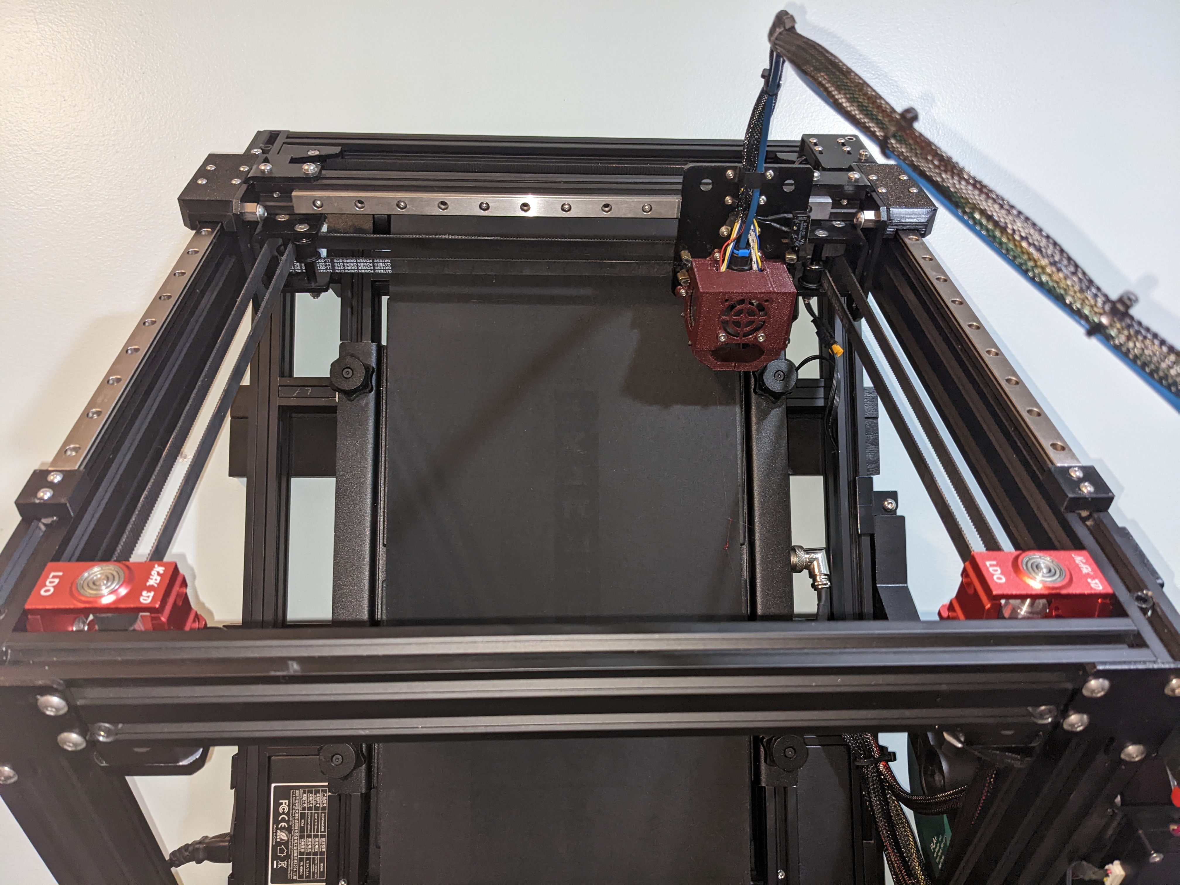
Updated 5-6-2023: At request I have updated this to add a version that uses a different brand of M5 Heated Insert with different dimensions. I also added a version that uses an M5 Nut for those that may not want to use a heated insert. Note: The name on the version of the M5 Heated Insert is based off the smallest outer "actual" dimension at the tip of the insert. But the actual hole dimension in the part is 0.2mm larger which is what I found works best for printing holes when using my printers. For example: The 6.3mm version will have an actual hole of 6.5mm and the 7.8mm version have an actual hole of 8mm. I am also updating the STEP file to which you can get into and edit things if need be. A mod to use Linear Rails on the Y-Axis of a CR-30 3D Printer. I designed this to be simple and easy. There are two parts that each need to be printed twice. The First is the Block Cover that attaches to the linear rail block and to the X-Axis. There are two versions of this part. One is for a MGN12 type "H" carriage block and one is for a MNG12 type "C" carriage block. They have different mounting whole spacing on the block so be sure to pick the one you need for your Linear Rail Block. The type "C" is the smaller of the two blocks with 20mm x 15mm spacing for the mounting holes. The type "H" is the larger block with 20mm x 20mm spacing for the mounting holes. The second part is just a square Stop to be placed at the end of the linear rail so the carriage does not slide off. Be very careful when mounting your linear rails. You do not want the block to slide off because you do not want to be picking up a bunch of small ball bearings off the floor. You can use these stops to prevent that and adjust them as need throughout the install process. Optional: There is also a small Alignment Jig I will upload you can print to center a Linear Rail on a 2020 Extrusion while screwing it down. They snap onto the Extrusion then just slide them over the Linear Rail to keep the rail centered on the Extrusion. They are not part of the mod, but just a tool to use to keep the linear rail centered on the extrusion. They can also be used to help keep the Carriage Blocks from sliding off the Rail. Parts needed: 2 @ MGN12 Linear Rails. 300mm to 350mm in length. Carriage Block Type "C" or Type "H" will work. 4 @ M5 x 20mm Cap Screws. 4 @ M5 Brass Heat Insert (8.3mm OD, 6.75 mm length) This size is what I used and designed the parts to use. 8 @ M3 x 10mm Cap Screws. 24 to 28 @ M3 x 10mm Countersunk Screws for the Linear Rails if you plan to use one in every hole. 300mm rails use 12 screws per rail and 350mm rails uses 14 screws per rail. Note: Countersunk screws are measured end to end and not the length of the threads so they will look smaller. 4 @ M3 x 12mm Cap Screws. 28 to 32 @ M3 Tee Nuts (4 to be used for Stop Block and the rest for the Linear Rails.) Parts reused from printer: 4 @ M5 Washers. 4 @ Eccentric Spacers. Install Instructions: (Pictures provided with make the install process easier to understand.) After Printing your 2 Block Covers & 2 Stop Blocks and getting the parts needed you can start the conversion. I found doing one side at a time worked best. 1) Prep the Printed Block Cover. Take your Heat Inserts and use a soldering Iron to carefully insert them into the holes on the side of the Block Cover. You want to do this first to give them time to cool down. Note: Make sure that the Heated Insert is flush with the outside of the print or very very slightly inserted. You do not want it to far in towards the linear rail nor do you want it sticking out of the print. 2) Temporarily remove the Y-Axis Metal Stop and Endstop Bracket from the printer. This is to make it easier to take measurements when installing the Linear Rails. 3) Slightly loosen the 2 screws on top of the Metal X-Axis Bracket. You can leave these loose until the very end of the install. 4) Start by removing the V-Wheels from one side. The X-Axis should hang there just fine. 5) Next remove the Eccentric Nuts. Mark the Eccentric Nuts with a Sharpie or make a scratch on it to know which side is the furthest out and which is the closest in. You will know what I am talking about when you look at the hole through it as it is off center. This is a Key part to do as the Cover Block Print is designed to use the furthest spread of the holes. Meaning the eccentric nuts will need to be reinserted making the screws the widest distance apart they can go. 6) Now reinsert the Eccentric Nuts on the "opposite side" of the bracket. Refer to the pictures provided to see their placement. Note: This may be a little tough. I had to clean out the holes on the other side of the bracket as it was a little tighter. probably do to paint and burrs. You can use a razor, file, or deburring tool for this. You might also look into using a longer M5 screw nuts and washers to compress the eccentric nut into place if you can not do it by hand. I had to do that for two of the holes on mine. 7) Once both Eccentric Nuts are installed make sure to rotate the Eccentric Nut so the holes are at their furthest spread. 8) Install the Stop Block you printed at the lower end of the slope on the Y-Axis Extrusion of the Printer using the M3 x 12mm Cap Screws and Tee Nuts. If the Printer is laying flat on the table it will be towards the back of the printer. If the Printer is mounted on a wall it will be towards the front of the printer. This is to rest the rail up against the Stops so that the Block do not slide off. 9) Measure the Distance between the Stop Block and the End of the Extrusion so that they are at equal distances for alignment purposes. 10) Prep the Linear Rail by installing the 10mm Countersunk Screws and Tee Nuts. 11) Carefully install the Linear Rail on the extrusion butting it up against the Stop Block. Before tightening down the rail you want to double check the distance measurement from the end of the Linear Rail to the end of the Extrusion so that they are equally placed and aligned. Make adjustments as needed. Then make sure to tighten down the rail. 11-1) Optional: If you wish to use the Linear Rail Alignment Jig for a 2020 Extrusion you can do so at this time for Step 11 to make sure that rail is centered on the extrusion. 12) Attach the Block Cover to the Linear Rail Block using the M3 x 10mm Cap Screws. Note: If the Linear Rail Block is not pre-installed on your Linear Rail, install it now using the manufactures approved method. Then attach the Block Cover. 13) Slide the Block with the installed Cover up to the X-Axis Bracket then take the M5 x 20mm Cap Screws and install a M5 Washers and then install them through the eccentric nuts and thread it into the M5 Heated Inserts. The Washers are there to make sure the M5 x20mm Screws do NOT touch the Linear Rail. It gives you that extra distance needed for this. 14) Repeat Steps "4" through "13" for the opposing side. 15) Once both sides are done Tighten up the screws you loosened on the Metal X-Axis Bracket. 16) The next step depends on if you did this mod laying flat on the table or mounted on the wall. The Stop Blocks need to be at the Front end of the CR-30 3D Printer. So if you had the printed Stop Blocks on the back end of the Printer you need to move the to the opposite side of the linear rails at this time. If you did this while the printer was mounted on the wall then you can leave them in place. 17) Reinstall the Metal Stop and Y-Axis Endstop Bracket at the back end of the CR-30 3D Printer. Note: I only used the (1) mounting screw at the top of the Endstop Bracket. This was advice from Pooch @Repkord. It is to allow for a better placement do to a screw within the Extrusion that gets in the way of the second mounting screw and tee nut for it. Check provided Pictures to see what I mean. What I personally did here to for the placement of the Metal Stop and Y-Axis Endstop Bracket was I lowered the bed all the way down. Then gave it a equal amount of rotations up. I think I did 2 rotations but can not be certain. Then I brought the Y-Axis to the bed with the nozzle touching the center of the bed. I used that position to slide the Metal Stop Block Cover and adjusted Y-Axis Endstop Bracket Placement accordingly. Then I adjusted the Bed Leveling and used the Endstop Adjustment screws accordingly allowing for the Y-Axis to home slightly above that Stopping point. This is just how I do my bed leveling mine. Everyone should fiddle with this to find a placement that they feel works for them and their printer. 18) The very last step is to double check your Belts to make sure they are tightened up. This is needed as things were moved within the motion system.
With this file you will be able to print CR-30 Y-Axis Linear Rail Mod with your 3D printer. Click on the button and save the file on your computer to work, edit or customize your design. You can also find more 3D designs for printers on CR-30 Y-Axis Linear Rail Mod.