CR-6 LGX Lite and Dragon Direct drive mount to the CR6 strain gauge
prusaprinters
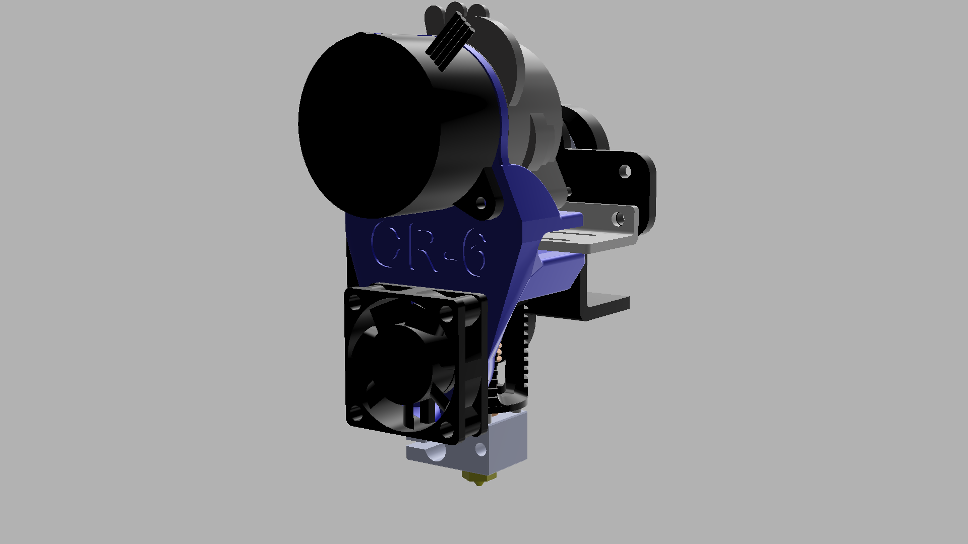
<h3> </h3><h3>Overview:</h3><p>This mount is part of a growing series of mounts for different hotends and extruders to the CR-6 strain gauge.</p><p>The series includes the Dragon, Mosquito and MicroSwiss hotends and the Orbiter V1.5, LGX Lite, Mjolnir and Bowden setup extrusion systems.</p><p>To be upfront: the standard LGX, Orbiter V2.0 and Superfly (and derivatives) cannot be supported as all are too bulky and collide with the X-carriage.</p><h3>Introduction</h3><p>This mount will strap the TriangleLabs and Phaetus Dragon hotend (both high flow and standard flow compatible) in combination with the LGX Lite extruder to the strain gauge of the Creality CR-6 SE and CR-6 Max (CR-10 Smart most probably works as well, please report if you are successful).</p><h3>Needed accessories</h3><h4>5015 blower fan</h4><p>The mount uses a 5015 blower fan. Please use the one posted here on Printables.com as part of the series:</p><p>https://www.printables.com/model/157511-cr6-5015-part-fan-shroud-dual-fang</p><p>The standard case and thus fan mount does not fit any longer. Since the 4010 blower is largely insufficient to properly cool and achieve good overhangs and bridging at reasonable print speed the fan is upgraded to a 5015 blower and a dual outlet fan shroud.</p><p>A 24V between 4000 and 6000 rpm 5015 blower fan is ideal. Higher rpm will be noisy. Also ball bearings are typically less noisy. The fan will typically be used at 60 to 80% of its maximum speed making operation nearly silent and keeping some headroom for improved cooling of overhangs and bridges.</p><h4>Daughterboard mount</h4><p>The daughterboard also interferes with the extruder and needs adaptation. Also for the daughterboard there is a special mount on Printables.org:</p><p><a href="https://www.printables.com/model/162434-creality-cr-6-daughterboard-mount">https://www.printables.com/model/162434-creality-cr-6-daughterboard-mount</a></p><h5><strong>Hot melt inserts</strong></h5><figure class="image image-style-align-center"><img src="https://media.printables.com/media/prints/126838/rich_content/1a6efedd-a174-4e73-8da7-6467eef066da/hotmelt.jpg#%7B%22uuid%22%3A%229e361644-b8c8-4540-97e3-df3d0856f1af%22%2C%22w%22%3A230%2C%22h%22%3A214%7D"></figure><p>4 M3 x 7mm (the model is 6 to 8 mm compatible) hot melt inserts. (4 x 7 mm for the extruder and strain gauge mount, the 2 for the hotend fan can be between 3 and 8 mm as they don't bear significant load). Take care to get real hotmelt inserts (with diagonal knurling's) as in the picture. The ones with straight knurling's are no good and are meant for injection molding not 3D printing.</p><h5><a href="https://www.aliexpress.com/item/4000232858343.html?pdp_ext_f=%7B%22sku_id%22:%2210000000945302171%22,%22ship_from%22:%22%22%7D&gps-id=pcStoreJustForYou&scm=1007.23125.137358.0&scm_id=1007.23125.137358.0&scm-url=1007.23125.137358.0&pvid=e707db28-7db4-41a2-b451-dc7f8a782c04&spm=a2g0o.store_pc_home.smartJustForYou_2001733901821.1"><strong>https://www.aliexpress.com/item/4000232858343.html?pdp_ext_f=%7B%22sku_id%22:%2210000000945302171%22,%22ship_from%22:%22%22%7D&gps-id=pcStoreJustForYou&scm=1007.23125.137358.0&scm_id=1007.23125.137358.0&scm-url=1007.23125.137358.0&pvid=e707db28-7db4-41a2-b451-dc7f8a782c04&spm=a2g0o.store_pc_home.smartJustForYou_2001733901821.1</strong></a></h5><p>A reference where you can buy them. There are plenty of other options. If you can prefer the M3 x D4.6 x L7.0 ones.</p><h5><strong>bolts</strong></h5><p>2 M3 x 10 mm bolts (extruder and strain gauge mount, max 12 mm otherwise the strain gauge will get damaged or the screw bottoms out on the hotend)<br>2 M3 x 16 mm bolts (hotend fan)<br>2 M3 x 24 mm bolts (part fan)<br>2 M3 x 5 to 8 mm bolts (daughterboard, not critical these can stick out)<br>2 M3 x 8 mm bolts (daughterboard mount)<br>1 M3 x 8 mm bolt (part fan shroud, not critical minimum 6 mm)</p><h5><strong>PTFE tube</strong></h5><p>21 mm PTFE tube</p><h3>Print instructions:</h3><p>Print in PETG, ABS, ASA or other high temperature filament. The mount cannot be printed in PLA as it will melt.</p><p>Print both the main model and the carriage plate hole template. The template will be used to drill a small hole in the carriage to easily fix the extruder motor.</p><p>Your printer has to be properly calibrated to get proper dimensional accuracy. Especially filament flow should be calibrated too high flow and the small holes will not yield the correct size, too little flow jeopardizes strength and stiffness. I advise to use the Cura “part for calibration” plugin and print the “multi-flow” test. SuperSlicer has the same test built in. For PrusaSlicer the test can be downloaded from GitHub: <a href="https://github.com/5axes/Calibration-Shapes">https://github.com/5axes/Calibration-Shapes</a> . Remark: this test uses .3mf files which have the flow settings built-in. The model should hence just be imported, sliced and printed. No flow settings for the individual bits need to be made.</p><h4><strong>Print settings:</strong></h4><ul><li>5 top and bottom layers</li><li>5 walls + alternative wall with infill</li><li>25% gyroid infill</li><li>line width 0.45 mm (outer line can be 0.4 for print quality)</li><li>no support needed</li></ul><p>The size numbers in the file names are the outer diameter of the hotmelts. Please check which OD hotmelts you have before printing.</p><h3>Assembling:</h3><figure class="image image-style-align-center image_resized" style="width:50%;"><img src="https://media.printables.com/media/prints/137422/rich_content/4c47b7b9-f871-4dab-b7a0-c9e4a8b963eb/20220319_132614.jpg#%7B%22uuid%22%3A%226d064ee9-e7d3-40fe-ada2-963e317770ee%22%2C%22w%22%3A2838%2C%22h%22%3A2695%7D"></figure><p>Take the backplate hole template and mount it on the backplate. Mark the position of the hole to be drilled (or predrill with a small drill). Drill a 4mm hole in the backplate. this hole will serve to insert the Allen key to fix the extruder motor. This can be done with the carriage still mounted but take care not to “shoot trough” when finishing the hole such as not to damage the carriage wheels.</p><p>A shortened Allen key is also possible but has proven to be a cumbersome solution.</p><figure class="image image-style-align-center image_resized" style="width:50%;"><img src="https://media.printables.com/media/prints/137422/rich_content/bd39e173-6e21-4fc4-ab36-8ae6de4cef86/20220319_130406.jpg#%7B%22uuid%22%3A%22d7b64ea2-ec18-4555-b9de-20c468b12b28%22%2C%22w%22%3A3000%2C%22h%22%3A3744%7D"></figure><p><strong>Hot melt inserts:</strong><br>Set 2 hotmelt inserts from the bottom of the mount to accommodate the strain gauge. and place 2 hotmelts for the part fan.</p><figure class="image image-style-align-center image_resized" style="width:50%;"><img src="https://media.printables.com/media/prints/137422/rich_content/8a8311d3-a9ec-40e2-b189-250807161965/20220319_130413.jpg#%7B%22uuid%22%3A%22d8d67a74-065b-4b4a-aba0-2a50fc76dc3b%22%2C%22w%22%3A3000%2C%22h%22%3A3744%7D"></figure><figure class="image image-style-align-center image_resized" style="width:50%;"><img src="https://media.printables.com/media/prints/137422/rich_content/6af286bc-7da4-4ced-8ee2-7bd2452c7f96/20220319_143527.jpg#%7B%22uuid%22%3A%22028f5208-249d-450b-afec-247c32d27c2c%22%2C%22w%22%3A3000%2C%22h%22%3A3744%7D"></figure><p>Mount the Dragon hotend to the printed mount using the with the 4 longer 2.5 mm bolts supplied with the Dragon.</p><figure class="image image-style-align-center image_resized" style="width:50%;"><img src="https://media.printables.com/media/prints/137422/rich_content/38b591be-22a0-43d9-8c23-91ccdf2f4c97/20220319_144249.jpg#%7B%22uuid%22%3A%22dfc7cb27-1857-4b1d-9588-da06c34e87ed%22%2C%22w%22%3A2712%2C%22h%22%3A2722%7D"></figure><p>Mount the mount with hotend to the strain gauge.</p><p>Insert the 21 mm PTFE tube. It should stick just 1 mm above the mount. A good idea is to carve out the top of the PTFE tube a little to make sure the filament will find the hole more easily.</p><figure class="image image-style-align-center image_resized" style="width:50%;"><img src="https://media.printables.com/media/prints/137422/rich_content/150f62c3-1918-46f6-b6b5-2ada8f557ed5/20220319_144306.jpg#%7B%22uuid%22%3A%225b35c579-9a7b-4a5b-b9c7-3ae5725382b4%22%2C%22w%22%3A2010%2C%22h%22%3A2021%7D"></figure><p>Remove the extruder motor spacer plate (the spacer plate is included in the printed model) and insert 2 square nuts in the left vertical side.</p><figure class="image image-style-align-center image_resized" style="width:50%;"><img src="https://media.printables.com/media/prints/137422/rich_content/dc2cc33e-30aa-4e40-bdcd-f76a996d89b5/20220319_144954.jpg#%7B%22uuid%22%3A%22c479ced8-530e-4101-b205-87cef679785a%22%2C%22w%22%3A2619%2C%22h%22%3A2792%7D"></figure><p>With a slight turning move set the extruder on the mount and bolt the motor to the extruder making use of the hole drilled before for the bottom screw. The top extruder screw is easily accessible.</p><p>Now fix the extruder with 2 more M3 x 12 mm bolts on the left side.</p><p>Now proceed to mount the part fan and daughterboard.</p><h3>Extruder motor direction</h3><p>Since the Orbiter is a geared extruder the extruder will typically run in reversed direction (aka filament comes out instead of going in). This is easy to correct by an adjustment of the firmware or just swapping 2 motor wires. Only one of the 2 should be done. If you are unsure this YouTube will detail it out:</p><figure class="media"><oembed url="https://www.youtube.com/watch?v=AgyNM7FQrmk"></oembed></figure><h4>Swapping wires</h4><p>Swap the 2 left hand wires OR the 2 right hand wires (not both sets of wires the motor will again turn in the same direction).</p><h4>Firmware change</h4><p>Sebazzz made a great tutorial how to change firmware of the CR-6: https://damsteen.nl/blog/2021/01/08/how-to-compile-cr6community-marlin-with-vscode-platformio Search for #define INVERT_E0_DIR and change it from false to true.</p><h3>Printing after installation</h3><p>Linear advance / Pressure advance (Marlin or Klipper respectively) must be retuned if you use these optimizations. The values will be very much lower. Sticking with the Bowden advance values will literally cause holes.</p><p>Especially retraction distance <strong>MUST </strong>be reduced significantly. Where the Bowden setup needs 3.5 to 6.5 mm retraction direct drive needs only 0.5 to 1.2 mm. Setting higher than 1.5 mm retraction values will cause molten plastic to be pulled into the hotend and thus very quick blockages. My favorite retraction tuning tool is: http://retractioncalibration.com set retraction distance to start at 0.1 mm and 0.1 mm increments.</p><p> </p><h3>edit 2022-02-26:</h3><p>Greatly improved hotmelt insert design based on manufacturer recommendations https://groov-pin.com/wp-content/uploads/2020/02/threaded_insert_brochure.pdf<br>I made a test part and am checking torque and creep resistance. The first indication is that this is better than with straight holes. In any case installing the hotmelt inserts is much easier due to the tapered hole</p><h3>Hotmelt sizes 4.2, 4.5&4.6 and 5 mm are now supported<br><br>edit 2022-04-04:</h3><p>minor update:<br>Slightly increased stiffness with an extra corner bracket on the right hand side.<br>Increased clearance of the mount screw for the daughterboard mount and slim down of the total width of the mount to save a little weight.</p><h3>edit 2022-04-12:</h3><p>Backplate hole template was missing its actual template hole - corrected.</p>
With this file you will be able to print CR-6 LGX Lite and Dragon Direct drive mount to the CR6 strain gauge with your 3D printer. Click on the button and save the file on your computer to work, edit or customize your design. You can also find more 3D designs for printers on CR-6 LGX Lite and Dragon Direct drive mount to the CR6 strain gauge.