CR-6 SE Dragonfly BMS mount modified for 40mm fan
thingiverse
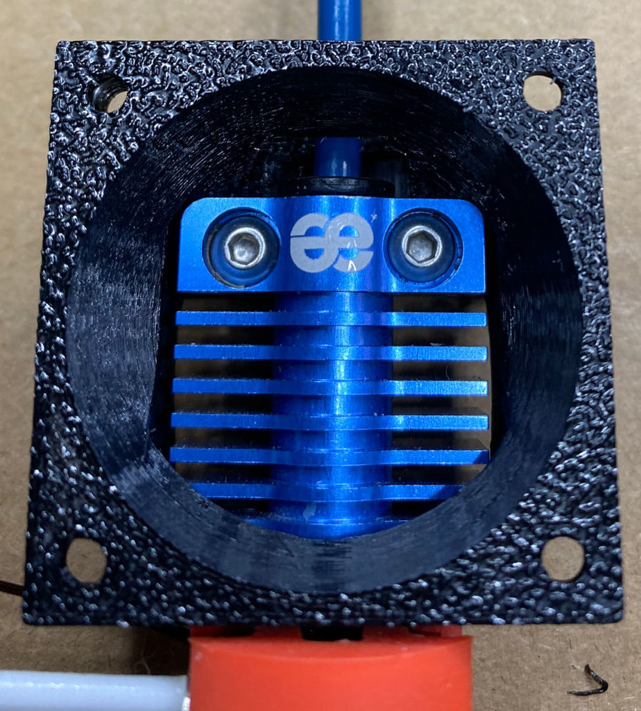
The .scad file requires the stock mount model from Phaetus, which can be found here: https://www.phaetus.com/wp-content/uploads/2021/01/BMS-for-CR-6-SE-1.zip I did not modify any of the stock Phaetus adapter model, beyond I did "patch" the holes that were used for mounting the stock 30mm fan and also shaving the front off a little to be able to add the fan shroud bevel. But the parts that contact the printer carriage and the BMS hot end are 100% untouched. Everything else was done from scratch using OpenSCAD (file included). Since the original model was not a community posted model, I did not label this as a remix. Although it technically is. If you use the OpenSCAD file to generate your own you can choose to generate 2 (top) or 4 (top and bottom) screw holes for mounting the fan. The STL I uploaded includes all 4 holes, you obviously can use whichever ones you want for mounting your fan I originally planned to mount a 20mm deep fan (4020) but that put me just outside of the space constraints within the stock metal cover, which meant I also would lose parts cooling until I added an external one. At this time I am pursuing a direct drive config which does not lend itself to adding an external parts fan until 1. someone publishes a DD model that includes a bracket for the parts fan or 2. I create my own. IMPORTANT: When mounting the fan, try to keep the end of the mounting screw behind the back of the front shroud frame. IE: Don't let the end of the screw extend past the back edge of the nut too far. This is only relevant for the top two fan mount holes, as they have the potential to interfere with the ABL movement. I have used some longer ones and they looked to be clear of the ABL, at least on my carriage, but it is best not to take any chances. That ABL movement is also why Phaetus put the raised areas on the top of the mount, where the screws that mount to the ABL sensor bar go through. That give the ABL sensor enough flex/movement between the mount plane and the top of the adapter/bracket. Sol it is best if nothing goes above the top of the flat part of the adapter/bracket. Parts list: (2) M3x10 to mount to ABL sensor bar (2 or 4) M3x16 to mount 4010 fan (2 or 4) M3x25 to mount 4020 fan (stock metal cover will not fit, off by just 1 or 2mm) M3 nut for each of the above screws used for me I also used 1 M3 lock washer for each, but Loctite or routinely checking tightness are also options. * Don't forget to put the nuts into the pockets for each of the mount points. When I first used the stock adapter there were no directions (not that any are really needed) but it took me a beat to realize that I needed nuts for the screws to, well, screw into. I found that depending on the printing tolerance when the adapter is printed that the nuts can get a little loose and spin in their sockets. Only matters when tightening or removing the screws, but I use a small drop of super glue to keep them in place. Just be careful not to glue the screws in or gum up the nut threads. I posted pictures of the stock adapter bracket next to my model for comparison. My observation is that it is a bit stiffer/stronger than the stock, likely due to the large frame I had to add to the front. I thought I had a picture of the BMS in the stock adapter, but I looked and do not. My one concern is that the bottom of the heatsink is partially obstructed by the bottom of the shroud. I originally had the shroud/frame centered on the back bracket (top to bottom), but the bottom of the front frame hung down a bit too close to the heat block/silicone sock and I was worried about the adapter "taking the heat". So I moved it up to where the bottom of the front frame, and shroud, to be flush with the bottom of the (original) bracket. This moved the inside cowl portion of the shroud up also. I am hoping that 1. the increased air flow from a 40mm fan coupled with the 2. more focused (funneled) air direction will more than make up for that while still being quieter than the stock 30mm fan. I will try to test it with a laser thermometer when I get it all setup, although I do not have any "before" metrics collected, so I will not have anything specifically to compare the new measurements against. This is a WIP. I have printed it but have not printed with it yet. I also have had to print this multiple times while working out the kinks. I found that the best printing orientation is with the front face (where the fan mounts) facing down on the print bed, with "all" supports turned on. It still cleaned up pretty easily using 30% support density. I also printed it in PETG with a high infill (I used 80%), 40mm/s speed and 1.2 layer height to improve dimensional accuracy and overall adhesion/strength NOTE: Triangle Labs Dragonfly is the Phaetus Dragonfly, they even reference it in their storefront. UPDATE: I just finished modifying it to open up the bottom of the shroud cowl for more air flow around the bottom of the heat sink. I just kicked off a print of it and will check it in the morning and update this post if it works out. UPDATE 2: v7 model and scad file up. Pictures of it installed will follow later
With this file you will be able to print CR-6 SE Dragonfly BMS mount modified for 40mm fan with your 3D printer. Click on the button and save the file on your computer to work, edit or customize your design. You can also find more 3D designs for printers on CR-6 SE Dragonfly BMS mount modified for 40mm fan.