Creality CR-10s Direct Drive
thingiverse
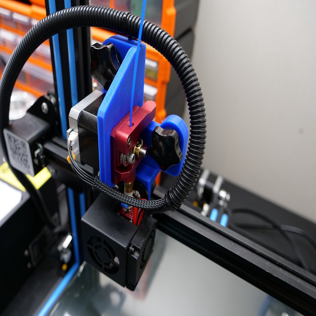
This project provides two 3D models to convert a Creality CR-10s 3D printer to direct drive. It uses the original extruder and stepper components by relocating them to the x-axis brackets. This project was created after I got tired of the filament sticking in the Bowden tube while printing on the stock Creality CR-10s printer (even after upgrading to a BondTech extruder kit). With the direct drive approach, the filament is pushed through only 60mm of Bowden tube rather than 400mm or so as in the original setup. Included Models: Mount_r01.stl Support_r01.stl Inventor Part Models: Mount_r01.ipt Support_r01.ipt Additional Parts: 2 M6 x 20mm Bolts 2 M3 x 8mm Button Head Screws 2 M3 x 10mm Button Head Screws 2 M3 Stepped Nuts 2 M6 x 30mm 5-Star Knobs 1 12mm x 600mm cable flex wrap 2 12mm cable mounts 4 Zip Ties Optional: Creality CR-10s extruder stepper extension cable 60mm Bowden tube section Tools: 2.5mm, 3mm and 4mm allen wrenches Drill motor 3mm drill bit Comments: With the exception of the additional parts, this conversion uses all original hardware so the direct drive can be converted back if desired. Note: The original extruder stepper cable can be used, but if the full vertical range of the printer (i.e. 400mm) is needed, a Creality CR-10s extruder stepper extension cable is recommended. Instructions: 3D print the two models with PETG filament Disassembly: 1) Remove the Bowden tube from the PC4-M6 fitting on the extruder. 2) Remove the PC4-M6 fitting from the extruder. 3) Remove the original extruder. 4) Remove the original extruder stepper motor. 5) Save the extruder and stepper hardware. 6) Remove the other side of the Bowden tube from the PC4-M10 fitting on the hot end. 7) Remove hot end cover. 8) Remove the hot end. 9) Loosen the x-axis belt tensioner and unclip the belt from the x-axis. 10) Remove the x-axis bracket. Note the position of the spacers between the brackets and the rollers. 11) Save the x-axis hardware. 12) Remove the filament mount from the control box. Prepare the Bowden tube 1) Carefully cut 60mm from the original Bowden tube (or use an optional 60mm section). NOTE: be sure to cut the Bowden tube exactly square. 2) Push the 60mm Bowden tube into the PC4-M10 fitting so that 26mm is sticking out from the bottom of the fitting (i.e. the hot end side of the fitting). 3) Install the PC4-M10 fitting w/60mm Bowden tube into the hot end. Note: the Bowden tube should touch the heat break within the hot end just before the fitting is completely tight. The tube will push up in the fitting the last little bit to ensure the Bowden tube is completely seated in the hot end. Assembly: 1) Reinstall the x-axis bracket and rollers using the printed support bracket in place of the original spacers. Snug the nuts on the rollers up, but do not tighten as the support will need to be aligned later. 2) Reinstall the belt ends and adjust the belt tensioner 3) Press the M6 x 20mm bolts into the two hex holes in the back of the bracket. 4) Install the hot end onto the original metal bracket. Do not tighten. 3) Assemble the stepper motor and extruder onto the 3D printed mount using the original hardware. 4) Install the PC4-M6 fitting onto the extruder. 5) Install the printed mount (w/stepper motor and extruder) using the 5-star knobs onto the printed support by inserting the Bowden tube into the PC4 fitting on the extruder. 6) Check the alignment while sliding the mount down and tightening the knobs. If the alignment isn't perfect; either adjust the support on the metal bracket or adjust the position of the extruder stepper motor in the printed mount, or both. 7) When the alignment is perfect (meaning the both PC4 fittings are aligned above each other in both directions), remove the hot end and tighten the roller nuts to secure the x-axis bracket and printed support. Tighten the extruder and stepper motor if previously adjusted. 8) Reinstall the hot end. 9) Reinstall the hot end cover. 10) Use the cable flex wrap around the extruder and hot end cables 11) Use the cable mounts and 2 M3x10 button head screw to fasten the wrapped cables to the support. 12) Enlarge the filament bracket using a drill and 3mm bit 13) Mount the filament bracket to the top of the printer frame using the M3x10 screws and stepped nuts. 14) Put the filament roll on the bracket and feed the filament into the extruder. Print a test part.
With this file you will be able to print Creality CR-10s Direct Drive with your 3D printer. Click on the button and save the file on your computer to work, edit or customize your design. You can also find more 3D designs for printers on Creality CR-10s Direct Drive.