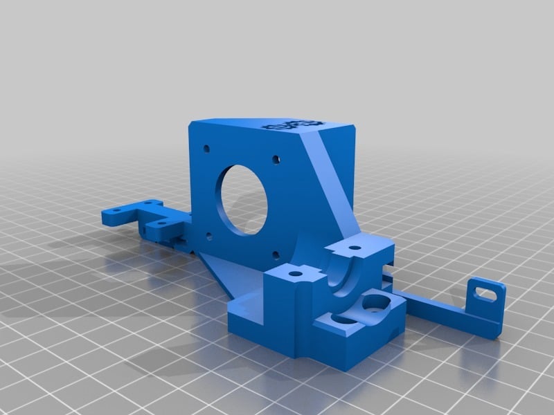
Creality CR-10S PRO E3D V6 Direct Drive Assembly
thingiverse
* **Update 8/7/2019**: **Version51_Base_Repaired.stl** has been uploaded. It is identical to **Version51_Base.stl**. The part had an issue when loaded into Cura 4.2.1. The model was repaired so that slicing would be more reliable. The model was handled correctly in Cura version 4.0.0 and so I was unaware that users with newer Cura installations might be negatively affected. * **Update 8/3/2019**: **Version51_Base.stl** has been uploaded. It further improves the part cooling fan mount and widens the clap mounting holes for easier assembly. **Version35_Clamp.stl** and **Version36_Clamp.stl** also have wider holes to accommodate the clamping screws. * **Update 7/27/2019**: **Version34_Clamp.stl** has been uploaded. It incorporates beams which span the half circle to better grip the hotend when tightened. A ring with a chamfered edge might be a better solution. **Version33_Clamp.stl** has been modified to reduce the number of triangles to improve file size. * **Update 7/25/2019**: **Version47_Base.stl** has been uploaded. Changes to the area of the part cooling fan mount. A change to the securing mechanism to aid in ease of positioning and a strengthened lower mount position. Be wary of electrical cables under strain. Strain is most evident with the heating cartridge wires since they are the most stiff and not as long as the other cables. Check that there is no strain at the plug/PCB connection when the hotend gantry is in the most right position (X-axis). * **Update 7/22/2019**: Use a more temperature resistant build material instead of PLA. The heat generated by the extruder motor is enough to soften its mount. PLA is still usable, it just might need monitoring for signs of fatigue. * **Update 7/21/2019**: **Version46_Base.stl** has added rib for support and rigidity. Much needed support to reduce flex due to the torque of the extruder motor. * **Update 7/20/2019 #3**: **Version45_Base.stl** nearing final release. Reduced height of filament sensor so that the overall assembly is more compact. Version44 is still suitable for download. * **Update 7/20/2019 #2**: Please use **Version44_Base.stl** It improves routing of the heater cartridge power wires. * **Update 7/20/2019 #1**: Please use **Version42_Base.stl** Critical changes were made to the part cooling fan section. Fan mounting positions were increase due to the stock blower assembly being lower than the nozzle. Improvements to the attachment mechanism were made as well. *** **The goal of this project was to design a drop-in replacement of the stock CR-10S Pro extruder and hotend. Wiring modifications and non-stock fasteners are required.** The Bowden extruder is now modified into a direct drive system. The whole assembly maintains the use of stock hardware like the filament sensor and dual gear extruder. The assembly has been designed to replace the stock hotend with the E3D V6 hotend. A wider array of nozzles can now be utilized as opposed to the stock unit. *** **Required hardware:** 2x M3-30 Hex Socket Head Screws (Securing V6 clamp to base assembly) 2x M3-10 Hex Button Head Screws (Securing base assembly to gantry using stock hotend mounting positions) Use the 2 stock button head screws used to secure the black metal fan shroud unit. 2x M3-20 Hex Button Head Screws (Securing part cooling fan) 5x M3 Washers (2x clamp, 2x base assembly, and 1x right stock fan shroud) 8x M3 Nuts (2x base assembly for clamp, 4x filament sensor, and 2x part cooling fan) 1-5 small zip-ties (Cable management) You will need to extend the wires for the stepper motor and filament sensor. **Installation Instructions/tips: (Attached photos with Step numbers)** - Step 1: Clear the X-axis gantry. It is a good opportunity to now check the gantry rollers. Ensure that they are secure and tight enough to handle the increase weight. Make adjustments by using the eccentric nut. - Step 2: Place the heating cartridge wires and temperature sensor wires through the channel running down the back side of the assembly. Be careful not to pinch the wires during this process. Secure the base assembly to the gantry using the three indicated mounting positions. Ensure that the part is level and secure as adjusting the part once assembled is difficult. - Step 3 and 4: TEDIOUS STEPS. Attach the hotend to the extruder using the shortened tubing (Step 3). Mock up the hotend-extruder assembly to the base in order to gauge when the proper distance has been met (alignment with the screw holes). Take your time as multiple adjustments might be required. - Step 5: Secure the extruder to the stepper motor with the three indicated screws first. Fasten tightly. - Step 6: Insert the final screw and spring components to finalize the extruder assembly. - Step 7: Correct extruder gear position so that it correctly lines up with the second gear. It will be misaligned due to the change in thickness of the stepper motor housing. *** **Potential issues:** Part cooling fan nozzle is too far right shifted. Might be a source of inadequate cooling. Z-axis origin based on nozzle position is shifted up from stock. X-axis gantry might clash with Z-axis stepper motors based on your configuration. Additional modifications are required if you have modified your printer by using Z-axis stepper motor lifts in order to install a dual Z-axis synchronizing belt. The Z-axis lifts, https://www.thingiverse.com/thing:3431219, can not be used in their default state. The lifts had to be decreased in height so that the base of the Z-axis stepper motors were no more than 11-12mm above the frame of the printer.
With this file you will be able to print Creality CR-10S PRO E3D V6 Direct Drive Assembly with your 3D printer. Click on the button and save the file on your computer to work, edit or customize your design. You can also find more 3D designs for printers on Creality CR-10S PRO E3D V6 Direct Drive Assembly.