Creality Ender-2 Controller Board (Labeled)
thingiverse
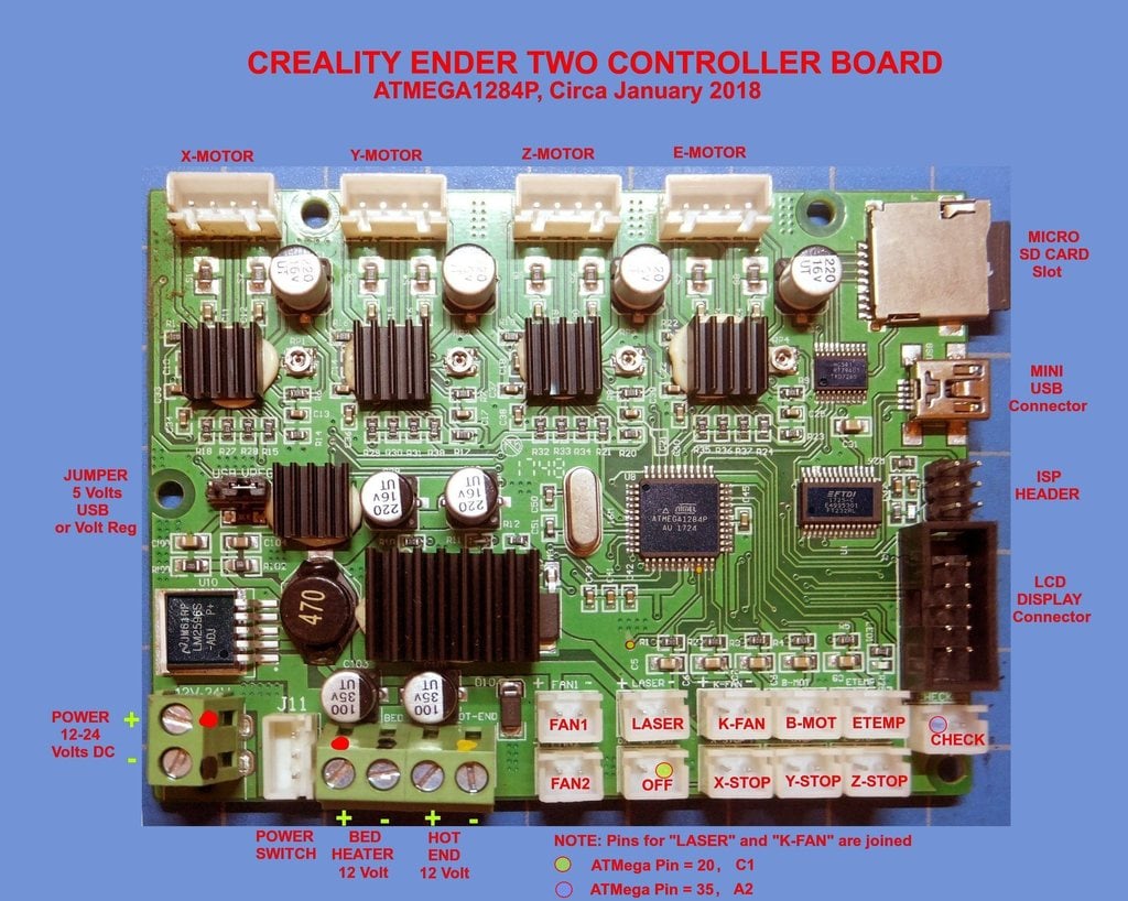
This is the PCB from my Creality Ender-2 circa January 2018. It is based on the ATMega1284P with a 16MHz crystal. I have added labels for all the connectors as well as inserting better captures of the top of each of the four main ICs in the picture of the top side of the PCB. The board is 100mm long by 75mm wide. I believe that for firmware purposes this board may be equivalent to the "Melzi (Creality)" as used in the CR-10 <i>(or at least a kissing cousin)</i>. The closest match I have found is the file "pins_MELZI_CREALITY_ENDER2.h" from TH3D Studio:\r\n\r\nhttps://www.th3dstudio.com/\r\n\r\n<u>Points of Interest:</u>\r\nThe only identifying label I can find is the "1748" number in the center of the board. My 'new' spare board has the number "1804" thus there is no identifying label for this PCB.\r\nAll fans are 12 Volt DC\r\n\r\n"FAN1" (hot end) and "FAN2" (controller fan) are always on.\r\nPins for connectors "LASER" and "K-FAN" are directly connected\r\nI believe that the "K-FAN" connector can be used for adding a part cooling fan. \r\n\r\nThe connectors labeled "OFF" and "CHECK" have no connections in the Creality Ender-2 printer.\r\n\r\nThe right pin (D17 on the PCB) of the connector labeled "OFF" is connected to Arduino Pin number 17 which is Port C1. Pin C1 is listed as "LCD_PINS_ENABLE" in the "pins_MELZI_CREALITY_ENDER2" pin definition file. The left pin (D27 on the PCB) is connected to Arduino Pin number 27 which is Port A4. Pin A4 is listed as "BEEPER_PIN" in the "pins_MELZI_CREALITY_ENDER2.h" pin definition file. \r\n\r\nThe left pin of the connector labeled "CHECK" is connected to Arduino Pin number 29 which is Port A2. Pin A2 is listed as "undefined" in the "pins_MELZI_CREALITY_ENDER2.h" pin definition file. The other pin is connected to the ground plane.\r\n\r\nMy intention is to use the "CHECK" connector for the I/O pin needed for the Geeetech 3D Touch sensor. Mounting bracket here:\r\nhttps://www.thingiverse.com/thing:2877869\r\n\r\n<u>USB BAUD RATE:</u>\r\nI had some trouble getting Repetier-Host to connect to this board. The problem was the baud rate. It should be 115200 <i>(or at least that's what worked for me)</i>.
With this file you will be able to print Creality Ender-2 Controller Board (Labeled) with your 3D printer. Click on the button and save the file on your computer to work, edit or customize your design. You can also find more 3D designs for printers on Creality Ender-2 Controller Board (Labeled).