
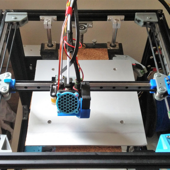
Creality Ender-4 Mega Rails Upgrade - linear rails at X and Y axes
myminifactory
Ender-4 Mega-Rails Upgrade, Step #9: Replacing all axes by Linear Rails The upgrade is large and challenging because many things to be changed at once. So, you have to be confident you are capable of performing it. Anyway, it's worth doing it. Summary of the Mega-Rails Upgrade: replaced all V-wheels of X and Y-axis by MGN12x300mm linear rails moved all moving parts inside the frame -> safer operations, less chances to put fingers in to a running belt moved motors to the front and inside the frame -> better space alignment (see pictures), less chances to skewed shafts b'cause motors are mounted close to the frame and supported by the frame replaced idle pulleys by pulleys with teeth -> decrease chance of micro vibrations caused by belt teeth running over flat pulleys surface designed idle pulley holders as a corner reinforcement element -> again, pulleys' axes are less prone to get skewed installed BLTouch instead of Induction sensor -> BLTouch allows switching bed surface easily: glass, mirror, etc... with no bed adjustments added a part cooling fan and duct: I have it now and it makes difference upgraded to optical X- and Y-end-stops -> more accuracy which is the must for a POWERLOSSRECOVERY feature universal Gantry Mount Plate that could accommodate different HotEnds (single, double) and other X-ends incl. direct extruder, milling, laser, etc. HotEnd Mount Plate can be easily adapted to other types of bed leveling sensors (I created corresponding designs, will share at Thingiverse) Also achieved: perfect alignment of motor & passive pulleys and the belt re-used printer parts as much as possible. shorter belt: cut 270mm (!!!) of the belt means less vibrations and more stabilitysmaller leverage/distance between pulleys on the left and right carriages: old distance was 50mm; new distance - 36mm -> means more round circles, less chances for ovals (linear rails sill have some tiny backlash and my previous "brutal" upgrade still produced ovals for small 3-7mm holes) lower weight of moving parts/gantry/carriages: removed parts: 432g, added parts: 394g = 34g reduction. Before this mega upgrade I made a "brutal" upgrade (search for Improvement #6) for Y-axis to liner rails and decreased the weight by 72g. So, comparing to the stock printer the overall weight reduction for moving X-rails and HotEnd gantry is 72+34 = 106 g. Thus, faster print speed could be achieved. Successfully tested 90mm/sec (45mm/sec for outer walls) without degrading a print quality. Drawback: reduced printing area to 210x210mm -> might be crucial to someone, but not that important to me. Also, I am considering some re-design of the right motor plate that currently interferes with the model fan duct. That would recover a bed Y-dimension back to 220. So, after all the print area will be 210x220mm... Parts to print: all parts at last 50% infill, Gyroid or Quarter Qubic, PLA or PETG except two parts close to HotEnd, for them ABS is the must all holes are tight and this is done by purpose to lock all bolts and prevent them from becoming loose. I do not recommend enlarging holes by a bore, just screw bolts in till they rotate freely 1 x Idle Pulley Corner Holder-Left (print vertically as it is shown at the picture, with support - Experiment tree in Cura) 1 x Idle Pulley Corner Holder-Right (same as above) would need: 4 x M5x8 bolt (mount to frame) 4 x M5x10 bolt (mount to frame) 8 x M5 Sliding Nut 2 x M4x25 bold (idle pulley axes) 2 x M4 Nut or lock nut 1 x MotorPlate-Left 1 x MotorPlate-Right 4 x M5x10 bolt (mount to frame) 4 x M5x14 Bolt (mount to frame, go through 2028 aluminum corner) 8 x M5 Sliding Nut 8 x M3x8 bolt (mount motors) 2 x Y-Carriage (left and right are identical) 8 x M3x8 bolt, Hex Head (mount to MGN12H carriage) 9 x M3 Nut (to mount top and bottom plates and end switch optical arm) 2 x Idle Pulley Plate-Bottom (print flat with support for nut and bolt place-holders) 2 x Idle Pulley Plate-Top (same as above) 8 x M3x8 bolt (to mount to Y-carriage) 4 x M4x25 bolt (pulley axis) 4 x M4 Nut or lock nut 1 x X-EndStop OptoSwitch Arm (print with support) 1 x Y-EndStop OptoSwitch Arm (print with support) 1 M3x8 bolt (to mount X-Arm) 1 x Y-EndStop OptoSwitch Mount (print with support) - developed for: http://got.by/3a7k6b 2 x M5x8 bolt 2 x M5 T-nut 2 x M3x8 2 x M3 nut 1 x X-Gantry (print vertically, no support, RE picture) 8 x M3 nut (insert to nut place holders to mount HotEnd plate and belt holders plates) 4 x M3x8 with a 90* flat head (to mount to MGN12H X-carriage) 2 x M2.4 screw (to mount X-optical stop switch) 2 x Belt Holder Plate 4 x M3x8 bolt (mount to X-Gantry) 1 x HotEnd Plate w BLTouch Holder (ABS!!!, print flat with support for nut place-holders) 4 x M3x8 bolt, Hex Head (mount to X-Gantry) 6 x M3 nut (insert to nut place-holders to mount HotEnd, HotEnd fan cage and BLTouch) I've shared a sketch of the HotEnd Plate, so that you may design your own X-Plates for any other extensions... (also may use DFX file for Fusion360). 1 x HotEnd Fan Cage, v2 (ABS!!!, print flat, RE picture, no support) borrowed and re-mastered from HeroMe at: https://www.thingiverse.com/thing:3092044 2 x M3x8 (mount to HotEnd Plate) 2 x M2.4 screws (mount to HotEnd Plate, on its top) 2 x M3x20 (mount HotEnd) 2 x M3x16 bolt (mount 4010 HotEnd fan and fan guard) 1 x 5015_Pipe (print flat, no support) borrowed from HeroMe at: https://www.thingiverse.com/thing:3092044 1 x M2.5x8 (mount to HotEnd fan cage) - salvaged from X-End stop 1 x 40mm_Hexaguard for HotEnd fan, borrowed from https://www.thingiverse.com/thing:2335067 Auxiliary parts: 2 x Rail_center_tool - to center linear rail while mounting it to the frame borrowed from https://www.thingiverse.com/thing:2170087 Overall budget: ~$60 USD (except bolts and nuts) BoQ: 3 x MGN12Hx300mm linear rail: http://got.by/34273a (3pcs) or http://got.by/3z1lk5 (2pcs) or http://got.by/3z1lng (1pcs) 2 x Pulley 20 teeth 2GT with 4mm bore: http://got.by/3z1lv8 (1pc) 1 x Opto-switch for X-axis: http://got.by/3czias 1 x Opto-switch for Y-axis: http://got.by/3a7k6b 2 x Opto-switches for DIY: http://got.by/3z1mdp (10pcs) 36 x M3x8 bolt, Hex Head: http://got.by/3z1mlv (50pcs) 25 x M3x8 bolt: http://got.by/3z1mut (50pcs) (may be hex head) 46 x M5x8 bolt: http://got.by/3z1myw (100pcs) or http://got.by/3z1n4q (50pcs) or http://got.by/3z1n90 (30pcs) 8 x M5x10 bolt: same as above 4 x M5x14 bolt: same as above 6 x M4x25 bolt: http://got.by/3z1nff (20pcs) or http://got.by/3z1nkv (30pcs) 2 x M3x20 bolt: http://got.by/3z1nqb (50pcs) or http://got.by/3z1nul (100pcs) 2 x M3x16 bolt: same as above 4 x M3x8 bolt with 90* flat head: http://got.by/3z1o35 (50pcs) 16 x M5 Sliding Nut: http://got.by/3z1ot7 (50pcs) 6 x M4 nut: http://got.by/3z1on6 (100pcs) 25 x M3 nut: same as above 24 x M3 2020 Sliding T-nut: http://got.by/3z1ot7 (50pcs) Bolts and Nuts Sets: M3 bolts Head Hex Socket and nuts set of 340pcs (M3-5-6-8-10-12-14-16-18-20): http://got.by/3z1p34 M4 bolts Hex Socke Set of 120 pcs (M4-6-8-10-12-16-20): http://got.by/3z1pba M3-M4-M5 Hex Head Cap, various sizes: http://got.by/3z1pi3 (20pcs) Aluminum corners: 4 x 2040 one-sided aluminum corner (on top of X&Y-motors mount, optional): http://got.by/3z1pm6 (5-10pcs) 20 x 20x28 aluminum corner: http://got.by/3z1pwv 40 x M5x8 bolt: http://got.by/3z1myw (100pcs) 40 x M5 T-nut: http://got.by/3z1q51 (50 or 100pcs) To do list: desigh plate for Y-end optical stop re-design 5015 duct to recover print area Y-dimension Additional Information: Motors re-connection: have to change direction of both X- and Y-motors because belt is now attached to the HotEnd gantry at the back comparing to the stock printer with the front attachment: flip X and Y-connectors by pulling out a white shell of the motor connector on the main board by a small pliers (metal contacts will stay on the board), turning the shell by 180 degrees and pushing it back on contacts (did it once for TMC2208; now, flipped them back to their initial state) motors are in front now as they were moved clockwise: left front motor in now Y; right front motor - X. Firmware changes: X-end switch: since end switches are all optical now, the X-switch should not be inverted (it is in the stock configuration): define X_MIN_ENDSTOP_INVERTING false BLTouch offset: define X_PROBE_OFFSET_FROM_EXTRUDER -27 define Y_PROBE_OFFSET_FROM_EXTRUDER 0 Inspired by: https://www.thingiverse.com/thing:2468019 https://www.thingiverse.com/thing:3145721https://www.thingiverse.com/thing:3331662https://www.thingiverse.com/thing:2170087 If you like my design, please, consider making a small "cup of coffee" donation using PayPal
With this file you will be able to print Creality Ender-4 Mega Rails Upgrade - linear rails at X and Y axes with your 3D printer. Click on the button and save the file on your computer to work, edit or customize your design. You can also find more 3D designs for printers on Creality Ender-4 Mega Rails Upgrade - linear rails at X and Y axes.