Crearibo Creality CR-10 Conversion to Linear Rods v1
thingiverse
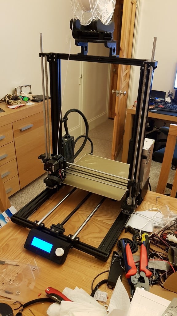
It seems like you're sharing a series of updates for a 3D printer project known as the Crearibo MK3, detailing improvements and changes made over time. Here are the updates in brief: 1. **Initial Updates (Nov 10, 2018)**: Initial setup with Z Motor Mounts, Top Mounts, Y Idler Mount, and Y rod holder. Nubs were added for better alignment. 2. **Subsequent Updates (Dec 10 to Nov 30, 2019)**: - December Update: Added information about print dimensions. - October Updates: Overhauled parts including Y rod holders, Z motor mounts, top mounts, and idler mount. Introduced the concept of a 300mm movement in the X-axis with new Z/X redesign. - January Update: Replaced old Y rod holders with revised models inspired by Zaribo style, eliminating the need for zip ties and adjusting alignment to fit better with MK3 hardware. - February Updates: Added nubs to Z mounts for easier installation. Introduced a step file for Crearibo MK3 v1, which requires no limit switches. - March Update: Included firmware files (Crearibo 7x7) compatible with MK3-based hardware. - April Update: Finalized the project's current state as Version 1, indicating further improvements might be considered in future versions. 3. **Additional Updates**: - Added a bed drilling template for CR-10 Mini. - Introduced a new Y Belt Holder that requires longer bolts and helps with belt alignment. - Updated Z axis parts to move the Z/X axis back towards the frame by 3mm, requiring a new Y belt mount. 4. **Final Update**: - Corrected BOM's and description. - Provided updated Z axis parts for better alignment and added a new Y belt mount to compensate for the change in the X-axis movement. The project seems to have undergone significant development with improvements aimed at reducing complexity, enhancing print quality, and adapting to MK3 hardware standards.
With this file you will be able to print Crearibo Creality CR-10 Conversion to Linear Rods v1 with your 3D printer. Click on the button and save the file on your computer to work, edit or customize your design. You can also find more 3D designs for printers on Crearibo Creality CR-10 Conversion to Linear Rods v1.