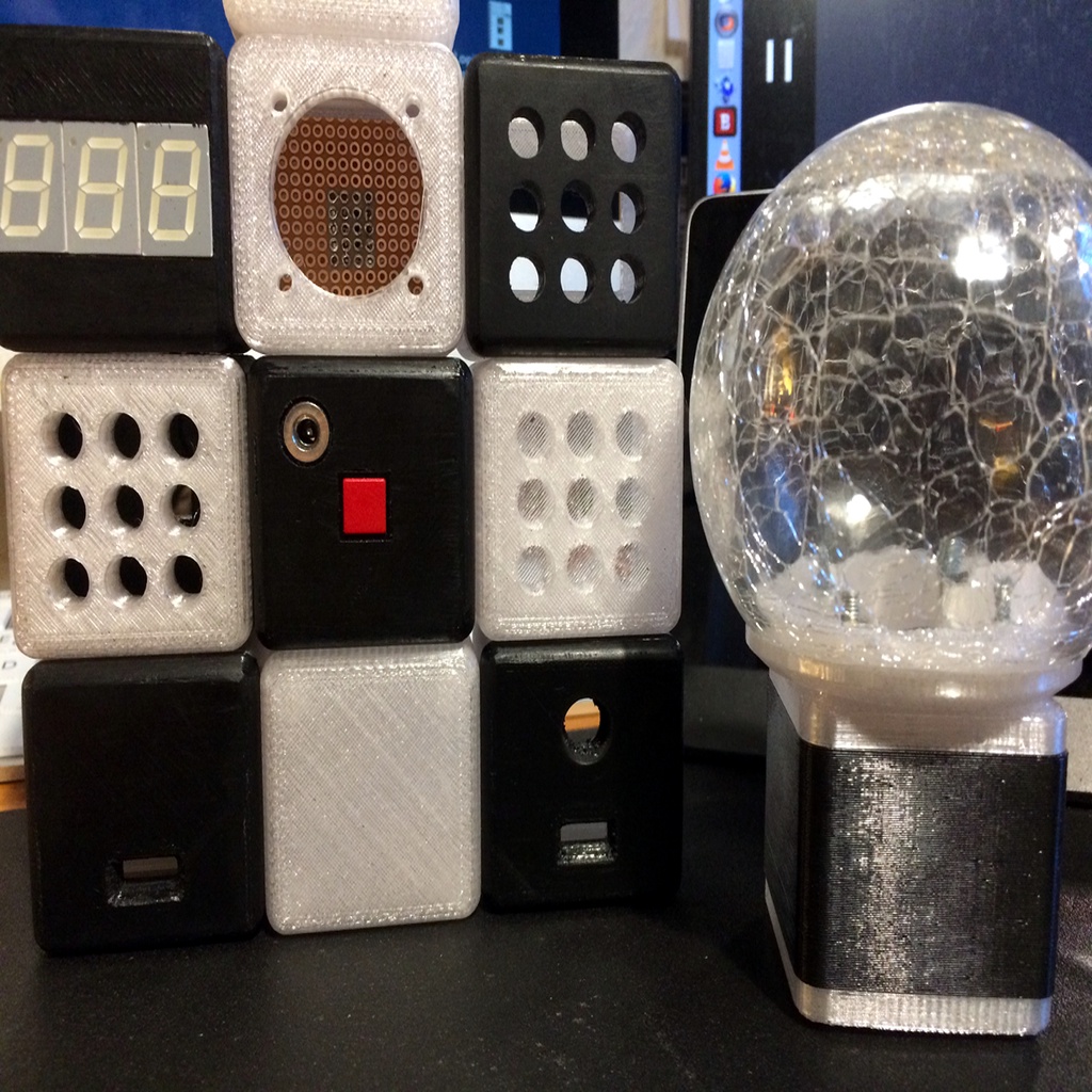
cube based system for decoration and technical applications
thingiverse
This text appears to be a collection of notes and hints related to building an electronic dice using an ATTiny13 microcontroller. The author provides details on various components, including 7-segment LED displays, power jacks, switches, and capacitive switch alternatives. They also share information about designing the PCB layout, stack PCBs, powering electronics with a super capacitor, and replacing mechanical switches with capacitive ones. Here are some key points extracted from the text: 1. Components: - 3* 7-segment LED TFK TDR5160 - 3.5mm DC Power Jack Socket Female Panel Chassis Mount - Momentary push button switch (C&K, RAFI, or Racon series) 2. PCB Design: - Size: 37x37mm for top and bottom parts, with rounded corners - Mid section and foot mounting plate can be up to 39.5x39.5mm 3. Electronics: - Power the ATTiny13 from a super capacitor (as described by Harald Sattler) - Replace mechanical switch with capacitive approximation switch To follow these instructions, one would need to: 1. Gather the required components. 2. Design the PCB layout according to the specified size and shape. 3. Implement the electronics using the ATTiny13 microcontroller and the super capacitor for power. 4. Replace the mechanical switch with a capacitive one. Note: The provided text does not include step-by-step instructions, but rather serves as a collection of notes and hints for building an electronic dice.
With this file you will be able to print cube based system for decoration and technical applications with your 3D printer. Click on the button and save the file on your computer to work, edit or customize your design. You can also find more 3D designs for printers on cube based system for decoration and technical applications.