Cudatox's Animatronic Tail
thingiverse
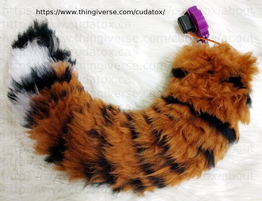
This is a complete set of STLs and OpenSCAD source files to build an animatronic tail. The scripts and source files are licensed for *non-commercial* use, please keep this in mind if you plan to make one for yourself. This tail consists of several plastic discs placed along a steel cable that acts as a flexible element and is actuated using cables connected to a servo. It is designed to be modular, adjustable and highly customizable. Most of the parameters in the OpenSCAD scripts affecting the appearance or motion of the tail can be tweaked and the design of the tail itself allows for parts to be easily moved, adjusted or swapped. In addition to the 3D printed parts, you will need: * A TGY-1501 (Or similar) Servo * Some Nylon coated braided wire fishing leader * A steel cable to use as your spine (I used 1/4" vinyl coated cable, but you may need to make adjustments to your tail depending on what you use) * A length of elastic cord (I used 4mm cord, but this is a tweakable parameter) * Some 3mm thermoset inserts * Adhesive for gluing plastic parts together * M3 screws, nuts, washers and square nuts. I mostly used M3x15 and M3x10 screws, but this will depend on the parameters you set in the scripts * Some means of controlling the servo. I used a custom made board, but there are many ways of accomplishing this. An assortment of M3 fasteners will likely have enough for this project, but I'd recommend getting some extra M3x10 screws and square nuts. __Rough assembly instructions__ __Attach the spine disks:__ Print out as many spine disks as you think you'll need, insert a square nut into the rectangular cutout in each of them. Slide the spine disks onto the steel cable, being careful to keep the holes for the control cables aligned along the spine. Insert a screw and tighten the disks onto the spine. Perform the same operation on the end piece, but also insert two square nuts for the cables. Use the photos for reference. __Glue the belt clip to the top of the pulley housing__ (see the exploded view). I used some epoxy to do this and it has held up for several years. __Attach the pulley to the servo:__ Screw the ROUND servo horn that came with your TGY-1501 servo into the pulley, but do not attach this assembly to your servo yet. You may have to use glue here if you do not have or cannot find an appropriate screw. __Install the threaded inserts:__ There are four M3 screws that hold the lid of the pulley enclosure to the housing. These require thermoset threaded inserts to be installed in the pulley housing, use the photos for reference to see which holes they need to be installed in. __Install the spacer and servo:__ Position the servo spacer (rectangular piece in the exploded view) over the servo cutout with the __grooved side facing out__. Place the servo on top of the spacer and fasten the servo to the housing. The heads of the screws should be __inside__ the housing. __Attach the spine clamp:__ The spine clamp is the lower most piece in the exploded view. First, insert a square nut into the rectangular cutout in the spine clamp, then screw an M3 screw into the corresponding hole. This does not need to be tight, it is simply to retain the nut you just inserted. Insert two square nuts into the rectangular cutouts on the pulley housing. position the spine clamp onto the pulley housing as show in in the pictures and secure it with some M3 screws. __Attach the spine to the housing:__ Insert the spine into the spine clamp and tighten down the screw you loosely tightened in the previous step until the spine is secured in place. __Do not over tighten, or it will be difficult to remove later.__ Pay close attention to the alignment of the control cable holes and the holes in the pulley housing. __Attach the cables:__ There's a cutout for a nut and a drill for a screw on the pulley. Insert a square nut and loosely tighten a screw into it. This is what secures the cable to the pulley. Take a length of fishing leader, folded in half and place it over the pulley. Tighten this screw down over it. feed the ends of the cable through the holes in the housing (the ones that pass through the spine clamp). This would also be a good time to check the length of your cables to ensure they are long enough. __Attach the servo horn:__ Plug your servo into your servo controller and center it. With the servo centered, orient the pulley so that the screw faces the top of the housing and attach the pulley to the servo using the screw that came with your servo. __Tension the cables:__ Feed the cables through the control cable holes in the spine disks. When you reach the end piece, Make sure your servo is centered and apply some tension to both sides of the cable before tightening down the set screws in the tail end piece that secure the cable. Screw the top of the housing on and you're done!
With this file you will be able to print Cudatox's Animatronic Tail with your 3D printer. Click on the button and save the file on your computer to work, edit or customize your design. You can also find more 3D designs for printers on Cudatox's Animatronic Tail.