D-Carve, a Different Printed CNC
thingiverse
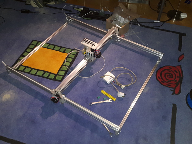
This text will become a total overhaul of the X-Carve CNC from Inventables (https://www.inventables.com/technologies/x-carve), relying solely on printed parts and easily obtainable components using V-Slot rails. Aside from the printed parts, bolts, and nuts, you will require: * 20x20 V-Slot rail - two pieces of the required length for the X axis * 40x40 from the 20 series (or two 20x40) V-Slot rail - length desired for the Y axis, identical to the previous * 20x40 V-Slot rail - two pieces, length as needed for the Z axis * 688Z bearings for XY wheels - a large quantity (the number of wheels multiplied by 2) * 604Z bearings for Z carriage wheels - 8 total * NEMA17 stepper motors - 4 (two for the X axis, one each for Y and Z axes) * 5 mm shaft pulleys - four in total (two for X axis, one for Y, and one for Z) * 8 mm shaft pulleys - two for the Z axis * ACME leadscrew and its corresponding nut - 1 (an M8 threaded rod can be substituted if the design is altered accordingly) * Timing belt - at least 10 cm longer than your X and Y rails, matched to your pulleys * Looped timing belt - must correspond with your pulleys and Z-axis motor plate Please consult the original X-Carve drawings for assembly (attached here) for clarity. UPDATE #1: Made improvements to the Z axis carriage stability; it no longer wobbles. The spindle is now attached via four M4 screws arranged as a square measuring 35x35 mm. Added mounts for DC and BLDC motors I am testing as spindles (as seen in pics) UPDATE #2: Added new carriage design using HIWIN rails, offering significantly more stiffness; added Dremel 300 and round router mount for both carriages; added tighter Z wheels and matching inner spacers; added drag chain and belt holders. Operational now. Initial tests underway! Pics demonstrate the machine milling out a creeper head from styrofoam using VISUALCADCAM Added laser line holders! First test video: https://youtu.be/rsAjviPOO2U (Machine generating its own wasteboard) Print Settings: * Rafts: Does not Matter * Supports: No * Resolution: 0.5 mm or lower, utilizing a single wall thickness for parts if desired. Both tool holders have different mounting holes; the laser line holder mounts on both sides, and must be within 2 mm spacing between the two carriage attachment points. Note to end-users: A few design decisions had to be made regarding assembly compatibility with existing Inventables files. As you build your X-Carve variant, verify that everything fits as designed and required modifications were indeed incorporated. The following text can help clarify or assist where changes need to occur: Roller Variant: ... (text remains the same)
With this file you will be able to print D-Carve, a Different Printed CNC with your 3D printer. Click on the button and save the file on your computer to work, edit or customize your design. You can also find more 3D designs for printers on D-Carve, a Different Printed CNC.