Deltabot 3D Printer
thingiverse
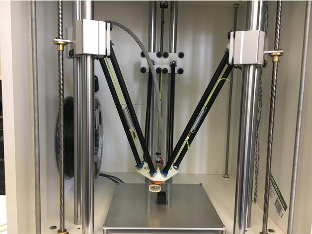
This is my first attempt at building a 3D Printer, which has been a learning experience. I set out a bit gung ho as I do without thoroughly researching what is out there in the thriving DIY community but have learned much in the process. I was attracted to the Deltabot design due to its symmetry and mechanical simplicity. A light weight, fast print head and a stationary build platform. Fortunately the more complicated software side has already been taken care of with many options available. Some of the things I'd like to improve for my second attempt would include: Smaller diameter linear rod. 20mm is clearly overkill, adds to overall weight and cost and consumes build volume for a given footprint. I'll be trying 8mm diameter linear rod next time. Lower the build plate. Currently the bottom 60% of the linear rod is unused as the carriages don't go down that far. I could make the push rods shorter, but this has effects on maximum speed possible. Having the build plate at the bottom of the rod is not cost effective in this regard - we could get away with half length linear rods and lead screws mounted higher. As above, we may need to relocate stepper motors to the top to accommodate shorter lead screws required. To follow on from this design, I would also like to attempt a CoreXY build, as this has similar advantages to the Delta design in respect to stationary stepper motors and lightweight print head but a much bigger build volume compared to the overall dimensions, particularly height. https://youtu.be/wAzyZs520Uk https://youtu.be/YuOwG7i-C38 note: The integrated carriages are not tested. Construction Outline Frame The critical piece of framework is the top and bottom sections supporting the linear rails. The columns must form an equilateral triangle and most importantly hold the linear rail perfectly vertical. I was a bit careless in measuring my triangle and ended up with an isosceles triangle which can be corrected in software, but I used some extra washers under the carriage pieces to correct for the misplaced rails. To begin, cut the two pieces, plus an extra for a drilling template, ensuring square corners. I used a circular saw to make the first cut. For this build I wasn't too concerned with chipping so left it at that for most edges. The three pieces were clamped together so the cut could be made in one pass. I also used a plunge router with a flush trim bit for finer control to tidy up some edges and square things off. Mark out the template with locations of the holes. A printable template may help. With one of the top or bottom sections carefully aligned with and clamped to the template, drill through the template and into the section using a Forstner bit in a drill press carefully aligned to be perpendicular. Set the depth stop so that the section is only partially drilled, say 6mm deep. The Forstner bit is suitable for drilling flat bottomed holes and also has a centre guide which may help if a small pilot hole is drilled first. Then swap to drill the other section on the opposite face of the template ensuring accurate alignment. I'm not sure if the Forstner bit would be sufficiently accurate on it's own if we first drilled pilot holes through without a template piece and then drilled the blind holes in the top and bottom sections individually with the Forstner bit. A template free alternative would be to clamp top and bottom pieces together and drill right through the top and partially into the bottom. Another piece or bracket can then be secured to the top to hold the rod in place. This would also ensure very good alignment of the holes vertically since they are drilled in one go. Various other holes for cable routing, motor mounts etc. can be drilled now or later. In my build, threaded rod clamps the top and bottom sections which both have blind holes drilled for 20mm linear rod. In this way, the bottom section is hanging from the top section which attaches to the rest of the frame. The rest of the frame is simple a box which is attached to the top section. Make it as square as possible. I recommend using a dowelling jig for accurate and consistent joins. Delta Joints Inspired by a Youtube video by Tim Jacobson showing non-magnetic ball and socket joints under compression, this design is somewhat similar, however the ball is to be glued in the effector socket to prevent wear on the printed components and the rod end slides over the ball. I'm still experimenting with rod ends, but for the moment I have capped the ends of 10mm carbon fibre tube with hot glue and used a piece of cloth between the rod and a 14mm steel ball bearing. Another option would be to glue a short piece of snug fitting (8mm ID, 10mm OD) PTFE tube to the outside of a smaller 8mm carbon rod to act as a rod end. The use of nylon or acetal balls would significantly reduce the weight of the effector, but care would need to be taken with the rod ends to prevent rapid wear. A thin teflon pad like that used by the BerryBot3D might be suitable. The string connecting the carriage to the effector is tensioned by small springs and hooks are used to facilitate easy assembly/disassembly. The joints hold quite well for printing purposes, however it doesn't take a lot of force to dislodge them. This is quite handy in the event of a head crash, as the rods will tend to pop out and the effector will hang loosely from the strings, rather than break. Hot End The hot end is constructed from two commonly available PTFE lined extruder barrels for 1.75mm filament. The hot barrel is cut down to allow the liner to pass straight through into the cold barrel. Between the two barrels are a couple of small spacers made from a piece of circuit board fibreglass cut into 5mm diameter discs with a 3mm centre holes act as a heat barrier and all three are threaded into a thermally insulating M6 threaded standoff. A piece of 10mm PEEK tube could also be drilled and threaded to act as a heat barrier in place of the standoff. A push fit tube connector is used on both ends of the bowden tube. They are available in the female variety, but most readily available are male. I drilled and tapped a male fitting to allow it to be threaded onto the cold barrel tube directly. Electronics Early on, I decided to beef up the motors to NEMA23 and used Chinese TB6600 stepper motor drivers, which actually turned out to be TB67S109AFTG based. After some debugging it was found that the direction signal passed through a low speed optocoupler which needed to be bypassed in order to prevent steps travelling in the wrong direction every time it changed. These are controlled by a BeagleBone Black running the Kamikaze distribution of Redeem and OctoPrint. I had planned to do it on the cheap and drive the whole printer directly from the BeagleBone Black IO, but when it came time to reimplement the MOSFET controls I decided to fork out for a Replicape board. The external stepper drivers are still necessary, as the Replicape can't deliver enough current to the motors on it's own. Bill of Materials This list will grow. I didn't really keep track of everything and did a lot of chopping and changing as the build progressed. 8mm Threaded Rod Aluminium Angle Extrusion 16mm Melamine Faced Chipboard 8mm Dowels SF20-500mm 20mm Hardened Round Linear Shaft - Alternative 8mm Shaft SC20UU 20mm Linear Ball Bearing Block - Alternative 8mm Bearings 500mm Lead Screw 8mm Thread 2mm Pitch Lead Screw with Copper Nut Brass Rigid Shaft Motor Coupling 8mm to 6.35mm 10mm OD Carbon Fibre Tube 14mm Steel Ball Bearings Small Tension Springs Bricklayers String Picture Hooks Cable Braid M6x30mm PTFE Lined Nozzle Throat 1.75mm MK8 Extruder 0.4mm Nozzle 25mm Height 6mm Thread 660V Busbar Insulator Support Connector - Alternative 10mm PEEK Rod 2x4mm PTFE Bowden Tube 4mm M6 Push Fit Connectors Nuts, Washers, Screws... Limit Switches Inductive Limit Switch Power Supply 24V 400W MK3 3D Printer Heated Bed Spring Bed Mounting screws B57560G104F 100K 1% NTC Thermistor NEMA23 Stepper Motor 1.26Nm 2.8A 23HS22-2804S TB67S109AFTG Based Stepper Motor Driver 4A (Advertised as TB6600) BeagleBone Black BeagleBone Black Prototype Cape Replicape Tools Used Drill Press Automatic Centre Punch Forstner Bits Plunge Router Flush Trim Router Bit Dowelling Jig Hacksaw Circular Saw Square Edge
With this file you will be able to print Deltabot 3D Printer with your 3D printer. Click on the button and save the file on your computer to work, edit or customize your design. You can also find more 3D designs for printers on Deltabot 3D Printer.