Deterministic Retraction Calibration
thingiverse
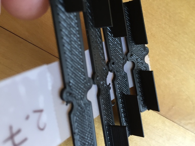
After building a new printer, I needed to calibrate retraction. I found, however, that current methods provided little help. Every calibration object I found had issues. I eventually decided that I would need to create my own calibration part. Towards that end, I came up with the following list of what I think makes a good retract calibration object: 1) As much as possible, a good retract calibration object should only test retraction. It should be mostly independent of other calibrations, and therefore easy to print. Many retract calibration objects require that printers be well calibrated for numerous other parameters. Some test retraction, but also depend on cooling, overhang, Z registration, extrusion flow rate, and other things. That not only makes the object hard to print, it also makes it difficult to say how well retraction is working. For example, cooling problems might result in pulling strings of molten plastic - that might look like a retraction problem where none exists. 2) It should be clear where retract and reload occurred on the calibration object, and what the travel was between them. Many retract calibration objects visually look like they will provide this, but fail in reality. When the GCODE is visualized, the extrusion path is complex. Retracts do not take place where expected, and travel after retract does not go where one would think. This makes it very hard to tell under what circumstances retraction is working. 3) The retract calibration object should give quantitative results. Many current objects give nothing more than a qualitative result. Although there is an indication that retraction is working to some extent, there is rarely an indication of the limits of that extent. 4) Printing the calibration object should not take much time or filament. Many current objects print much more than needed to evaluate retraction. 5) Ideally, it should be possible to customize the calibration object to better suit specific printer needs. After a number of failed attempts at designing a good test object, this calibration part is the one I have settled on. For me, it meets all of the above requirements. The print is very easy and forgiving, and gives a clear indication of how retract is working for specific gap sizes. I have already made big improvements using this object, and expect to make more. The OpenSCAD source is included with parameters to make customization easy should you need different settings from the ones I used in producing the included STL files. Print Settings Rafts: Doesn't Matter Supports: Doesn't Matter Notes: Set the extrusion width to 0.65mm so that the fin sections are a single width wide. If 0.65mm is not reasonable for your printer, use the OpenSCAD file and adjust the parameters to a width that works for you. Plate multiple of these at the same time so that cooling is not an issue. I generally plate all of the small gaps (1mm-5mm) as one print, and then plate all of the large gaps (10mm, 20mm, 30mm, 40mm) as a second print. That seems to work pretty well. Print settings should be very forgiving. One of my main goals was for this to be able to be printed even if a lot is off on a printer. It does need some basic printing ability, but the exact settings should not be that important. I recommend watching the print to make sure that: 1) The retract is happening on the side marked retract (indented in base) and reloading on the side marked reload (bump in base). If this is not the case, either use the OpenSCAD file to flip those markers (there is a parameter to do it), or just be aware which side is which. 2) The travel is as expected. On any given part, a line of one fin should print, retract should take place, the print head should move directly across the gap, reload should take place, and then the second fin should print. Sometimes slicers do odd things. I have tried to force the behavior on this object, but your mileage might vary - so verify this is giving you useful information. If the print order is not correct, your slicer might have an option to print each plated object individually, and that might resolve the issue. 3) The retract and reload should not be doing anything visually odd. When I started working on retraction, I found the print head would sit for far too long at the retract and reload points. That was useful calibration information by itself. I find the large gaps are most appropriate for determining the best retract length. I look for the smallest amount that will make all gaps come out clean. More than necessary is not beneficial, so try to find the point where results are not good enough and then increase the retract just a little. I find the small gaps are better for things like speed, temperature, and minimum travel after retract.
With this file you will be able to print Deterministic Retraction Calibration with your 3D printer. Click on the button and save the file on your computer to work, edit or customize your design. You can also find more 3D designs for printers on Deterministic Retraction Calibration.