Dewalt 20v Max power tap
prusaprinters
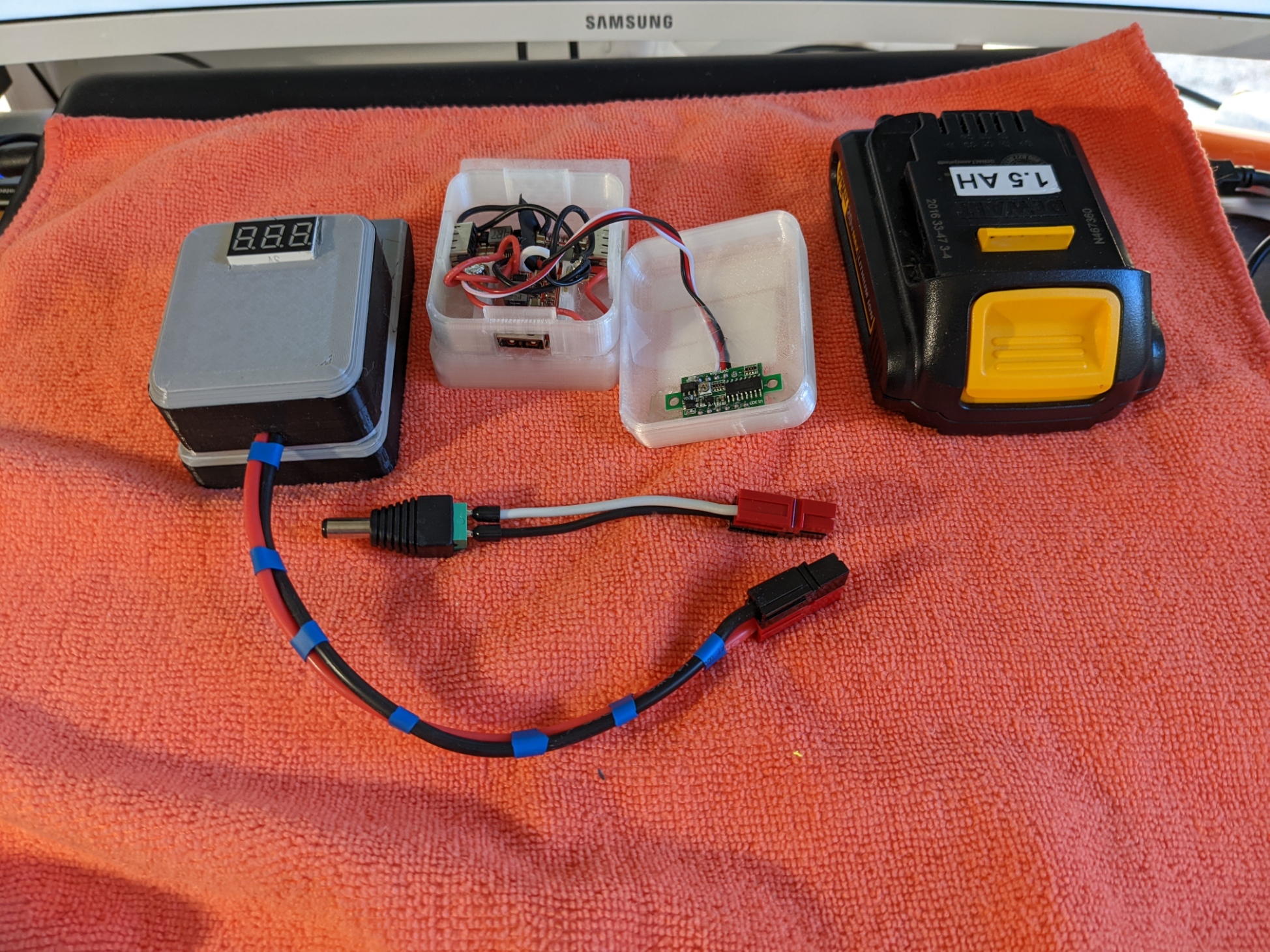
<p>These components can be assembled, by stacking, to construct various items powered by the Dewalt 20v max batteries. Three examples in the pictures are a power tap with anderson powerpole connectors, a power tap with a pigtail, and a three place USB 5v 3A charging stations. Configurations can include a cap with a cutout for a voltage readout.</p><p>In the examples shown, the voltage readout was of this type: <a href="https://www.amazon.com/gp/product/B00YALUXH0">https://www.amazon.com/gp/product/B00YALUXH0</a></p><p>The USB 5v chargers were of this type: <a href="https://www.amazon.com/gp/product/B01HXU1C6U">https://www.amazon.com/gp/product/B01HXU1C6U</a></p><p>The Anderson powerpoles used are this style connector: <a href="https://powerwerx.com/anderson-powerpole-connectors-30amp-unassembled">https://powerwerx.com/anderson-powerpole-connectors-30amp-unassembled</a></p><p>The battery connection terminals were cut from 1" x 1/32" brass stock. Each was an 8 - 9 mm slice off the end. For me, the easiest way to cut was to scribe on both sides, then use pliers gripping next to the scribed line to flex back & forth until the piece fractured off.</p><p> </p><p>The components consist of the following, all named “dewalt 20vmax power tap” with an appended identifier.</p><p>Part Description</p><p>A - the base component that engages the battery</p><p>Bn - a middle layer component that is attached to A via two 3mm screws</p><p>B1 - version with two cutouts to accomodate USB charger boards</p><p>B2 - version with one cutout to accomodate a USB charger board</p><p>B3 - version with one cutout to accomodate a pair of 14 awg wires.</p><p>B4 - version with one cutout specific to accomodating a joined pair of Anderson power pole connectors. It has a pair of ribs that engage the depressions on the connector sides to hold them securely in place.</p><p>Cn - a component that snap fits to a B component. It may be a cap or expansion space.</p><p>C1 - A cap with a solid top.</p><p>C2 - A cap with an opening sized for a voltage display.</p><p>C3 - An expansion space to accomodate a device up to 80mm x 50mm x 17</p><p>Dn - A cap for a C3 component</p><p>D1 - Solid cap</p><p>D2 - Cap with opening for voltage display</p><p> </p><p>All components should print without need for supports. The electrical contacts should be mounted through both A & B components used. Users may want to include an appropriate fuse for their application, either internally or externally. I used servo tape for securing electronics in place.</p><p>Some early versions seen in the pictures had A&B components glued rather screwed together. Using screws limits the USB charger build to two ports rather than three.</p><p> </p><p> </p><p> </p><p> </p>
With this file you will be able to print Dewalt 20v Max power tap with your 3D printer. Click on the button and save the file on your computer to work, edit or customize your design. You can also find more 3D designs for printers on Dewalt 20v Max power tap.