DIP-28 IC System Access Gadget
thingiverse
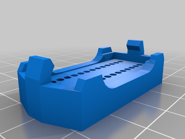
I'll start off with the fact that I had quite a hard time finding a Name for this thing. It's basically an adapter, which lets you reconfigure the Pins of any 28 Pin DIP-IC (I use it for the Atmega8), in an already existing system. You can put the controller (or whatever thingy you have there) on a breadboard, and plug the System Access Gadget (SAG)into the controllers socket on your circuit board. Then you just wire up the pins, and reconfigure them as you please (ad something, leave something out). The Second part is basically a comb to keep your cables in line, and I made it a bit bigger so you can label the pins with a CD-Marker. This way you can put pretty long cables on it, without having to trace every single one from the very root when you want to wire up the other end. It helped me a great deal, so I thought I put it up for everyone. Just in case I'm not the only one who etches his circuits a bit prematurely. If you find it useful, please leave a comment. Instructions I think this should be a fairly uncritical thing to print, only for the last few layers, where it's doing the snap-on arms, you should make sure your printer doesn't print so quickly that they melt and deform. I printed with PLA, 0.2mm Layer height, 3 solid layers and 3 Walls, 25% rectangular infill. Then you just take one of these PCBs for prototyping (see picture) and a row of RM2.54 Pins, and some thin cables (mine are ca. 1mm on the insulation, but I had to make the holes in the print 2.2 to make them fit) The PCB has to be cut down to a 38x18(+0/-1) rectangle, and if you use the same type as me, don't forget to cut the copper in the center because you do not want to link the left and right pins together. Then you cut your wires to length, I recommend 40 - 50cm (mine are 25, and they are a bit short), break your pin arrays to length, and solder: Pins. Important that you do these first, as your cables might get loose again if you solder the pins second. All the wires. I used different colors for every port, and Red/Black for Vcc/GND At this point I would recommend you label the pinholes on both pieces, as long as there are no cables in the way. I only put pin numbers on the small one, the "mask" is large enough to write down port-designations. Then you fiddle the wires through the clip from below (Copper pointing towards the plastic!), and, while pulling them through, you clip the board on. Might take a little effort to get it right. All the cables go through the rounded openings at the sides (see pictures). Then the same for the mask, and once all the wires are through, and you are absolutely sure none are misplaced, I recommend soldering some kind of metal pin to them (I destroyed an IC socket for the nice turned ones, but they are a little short for the old, worn out breadboard I use), and cover the soldered spot with heat-shrink insulation. Viola [sic], you are ready to go!
With this file you will be able to print DIP-28 IC System Access Gadget with your 3D printer. Click on the button and save the file on your computer to work, edit or customize your design. You can also find more 3D designs for printers on DIP-28 IC System Access Gadget.