DIY GREENHOUSE by KMS
prusaprinters
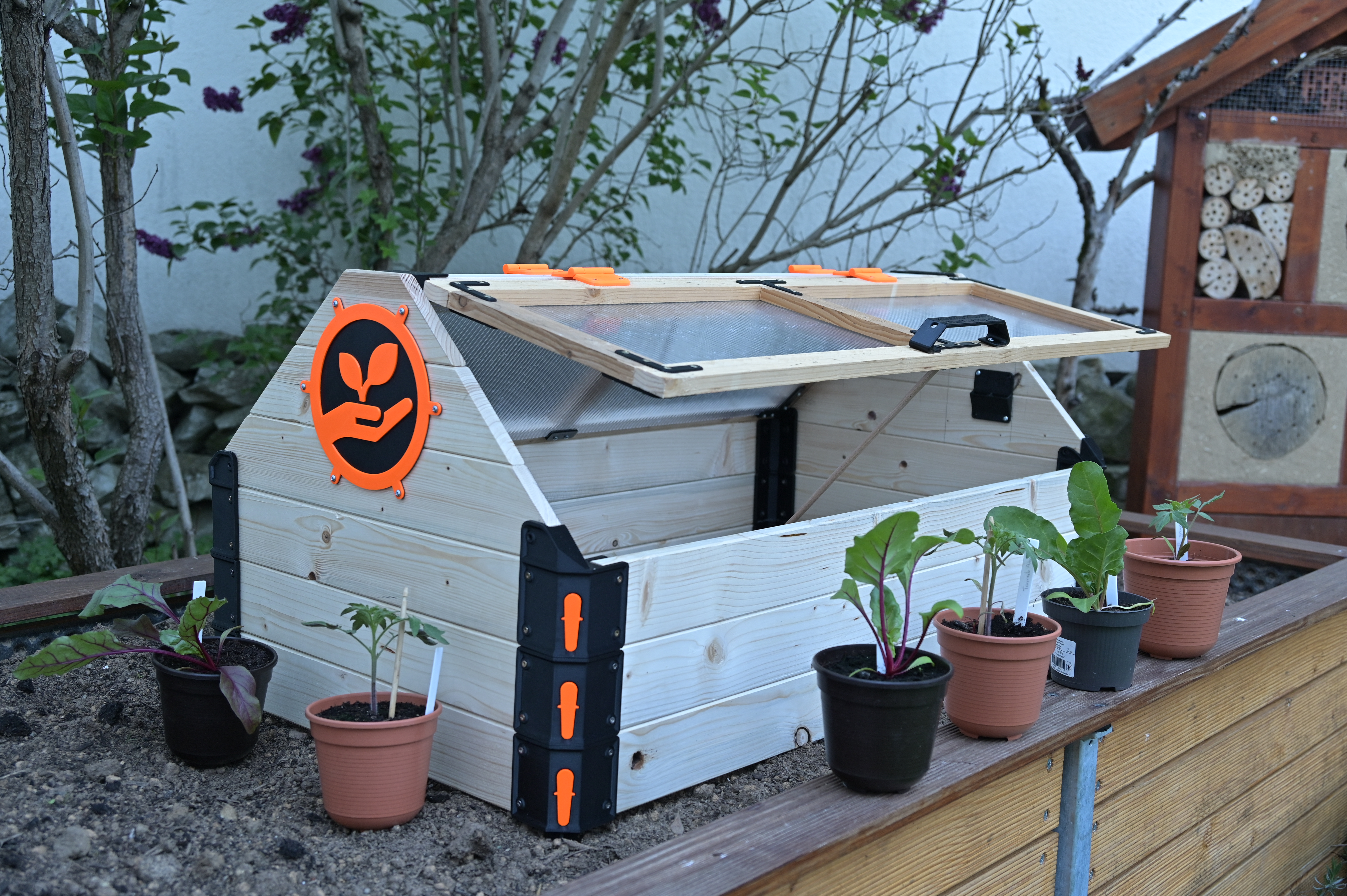
<h3>About:</h3><p>The modular construction allows you to adjust the greenhouse to your needs (instructions with dimensions at the end of the text for the greenhouse shown). The combination of wood and 3D printed parts makes this possible. </p><figure class="image image-style-align-left image_resized" style="width:50%;"><img src="https://media.prusaprinters.org/media/prints/62627/rich_content/589e6e62-b58a-4aa4-bce2-a834beb29059/dsc_8373-2.jpg#%7B%22uuid%22%3A%22a1e0e4e1-23b9-47df-be82-2e568f9a3097%22%2C%22w%22%3A4856%2C%22h%22%3A3296%7D"></figure><p> </p><p>The length of the boards determines the size of your greenhouse. The corner modules connect the boards to a frame. You can then stack the frames on top of each other as you wish. The individual frames are connected by a locking mechanism. The mechanism consists of a 3D printed spring and a lever (if you only want to test the mechanism, you can print test components from the test folder). </p><p> </p><figure class="image image-style-align-right image_resized" style="width:50%;"><img src="https://media.prusaprinters.org/media/prints/62627/rich_content/a46a4e20-9bbe-46b4-b5db-3fe8014230c7/dsc_8383-2.jpg#%7B%22uuid%22%3A%22fcef038e-581b-4283-b4ba-f0b41bf04a53%22%2C%22w%22%3A5124%2C%22h%22%3A3273%7D"></figure><p> </p><p>The last module you can add is a roof that you can open from two sides. The hinges used are also 3d printed parts and can be printed as a single part. The tight tolerances guarantee a secure guidance of the roof flaps. The crossbar is inserted via a dovetail. The fittings (logos) connect the boards of the roof gable. </p><p> </p><p> </p><figure class="image image-style-align-left image_resized" style="width:50%;"><img src="https://media.prusaprinters.org/media/prints/62627/rich_content/f1d8b56d-aef1-4918-a5ca-d9346279c1ee/dsc_8394-2.jpg#%7B%22uuid%22%3A%224bc7efd3-1402-47b8-8b0b-aa997491f911%22%2C%22w%22%3A4830%2C%22h%22%3A3046%7D"></figure><p> </p><p>With the earth spikes you can place the greenhouse securely in the patch. </p><p>Alternatively, you can install a floor. In the future there will also be a frame so that you can place the greenhouse as needed. (Not yet satisfactorily implemented due to time constraints)</p><p> </p><p> </p><p>The boards used for the frame have a height of 80mm and a width of 18mm. The roof slats of the roof flaps have a height of 35mm and a width of 16mm.</p><p>I have provided you with all the step files so that you can adapt the parts to your case if necessary. If you have any questions about this project, please feel free to contact me and I will do my best to help you with your own project.</p><p>There will be further updates on that project asap. Check: <i>DIY GREENHOUSE by KMS_Changelog.pdf</i>.</p><p>Happy printing and stay tuned :D</p><p>Yours <strong>K</strong>ERLE <strong>M</strong>AKER<strong>S</strong>PACE</p><p><i>PS: Feel free to support my work by liking or leaving a comment.</i></p><h3>Updates and Upgrades</h3><figure class="table"><table><tbody><tr><td><strong>Change / Update</strong></td><td><strong>Release</strong></td><td><strong>Version</strong></td><td><strong>Change</strong></td></tr><tr><td>Adjustable window support</td><td>06.06.2021</td><td>1.0</td><td>new feature added</td></tr><tr><td>Update greenhouse (basic)</td><td>11.06.2021</td><td>0.1</td><td>Plantindicator / gabel supports reworked</td></tr><tr><td>Rack and Floor</td><td>in progress</td><td>2.0</td><td> </td></tr></tbody></table></figure><p><strong>1.0 Adjustable window support</strong></p><figure class="image image-style-align-left image_resized" style="width:52%;"><img src="https://media.prusaprinters.org/media/prints/62627/rich_content/66ffa1a2-2384-4e93-8950-874d6abcaf9a/bild1.png#%7B%22uuid%22%3A%22b9326fd6-4bae-463f-aa6c-cd25207ba04a%22%2C%22w%22%3A2000%2C%22h%22%3A1051%7D"></figure><p>To better regulate the temperature in the greenhouse on hot days, you can open the roof flaps. With the new update, you can now easily keep the flaps in different positions so that an optimal position is achievable. The rotating clamp enables a very flexible installation of the system, as it always adapts to the opening angle. You can fix the position with a knurled screw. </p><p>(STL- and 3mf-Files provided)</p><p> </p><p><strong>0.1 Update Greenhouse (basic) – revised “plantindicator”</strong></p><figure class="image image-style-align-left image_resized" style="width:50.39%;"><img src="https://media.prusaprinters.org/media/prints/62627/rich_content/0af4efd1-02fb-4dc9-bae6-41f86c6065c7/_dsc7800-2.jpg#%7B%22uuid%22%3A%2249071e84-d0a4-400b-ac12-0609bf693aac%22%2C%22w%22%3A3205%2C%22h%22%3A2034%7D"></figure><p>For better stability, support plates are mounted on the inside of the gable. It was brought to my attention from the community that the old indicator was misleading. Therefore I have revised the design. With the revised version you have two options. Either you use only the support plate or the plant lable with the spikes that can be practically used to labe the plants.</p><p>(STL- and 3mf-Files provided)</p><h3> </h3><h3>Assembly:</h3><p> </p><h5>0.0 DIY-Greenhouse Basic</h5><figure class="table"><table style="border-bottom:solid;border-left:solid;border-right:solid;border-top:solid;"><tbody><tr><td><figure class="image image-style-align-center image_resized" style="width:50%;"><img src="https://media.prusaprinters.org/media/prints/62627/rich_content/ebe27b28-734b-46c4-a173-66ef5d88d93b/_vev9257.jpg#%7B%22uuid%22%3A%220933136d-d1c7-4e5e-8862-8e36b312ca45%22%2C%22w%22%3A3696%2C%22h%22%3A2448%7D"></figure></td><td><figure class="image image-style-align-center image_resized" style="width:50%;"><img src="https://media.prusaprinters.org/media/prints/62627/rich_content/4505e99b-48fa-47ad-b418-101be41d40f7/_vev9259.jpg#%7B%22uuid%22%3A%22f63f059c-f2f2-4fe4-b43f-7348226195b5%22%2C%22w%22%3A3696%2C%22h%22%3A2448%7D"></figure></td></tr></tbody></table></figure><p>The printed spring must be freed from the support structures. It is best to use Knippex pliers for this. The support structures break out easily</p><p> </p><figure class="table"><table style="border-bottom:solid;border-left:solid;border-right:solid;border-top:solid;"><tbody><tr><td><figure class="image image-style-align-center image_resized" style="width:50%;"><img src="https://media.prusaprinters.org/media/prints/62627/rich_content/033995d1-4337-4c0b-a8b3-7f6c8a3a2453/dsc_8418.jpg#%7B%22uuid%22%3A%225f61fee6-0aff-49b9-8f2d-9d8856a05af6%22%2C%22w%22%3A4482%2C%22h%22%3A3053%7D"></figure></td><td><figure class="image image-style-align-center image_resized" style="width:50%;"><img src="https://media.prusaprinters.org/media/prints/62627/rich_content/1db3aabd-2168-4500-b4d7-ccf2aaf34d50/dsc_8419.jpg#%7B%22uuid%22%3A%226ca3d043-0e25-4ad0-93f9-cedb25bd5b13%22%2C%22w%22%3A4483%2C%22h%22%3A3006%7D"></figure></td><td><figure class="image image-style-align-center image_resized" style="width:50%;"><img src="https://media.prusaprinters.org/media/prints/62627/rich_content/8c4d7733-567f-483e-a538-38277c391599/dsc_8420.jpg#%7B%22uuid%22%3A%22d3398bff-019b-48d1-8aad-7322cd2ad121%22%2C%22w%22%3A5135%2C%22h%22%3A3190%7D"></figure></td></tr></tbody></table></figure><p>When assembling the mechanism, insert the spring and insert the lever sideways and push it in. Finally, operate the lever several times.</p><p> </p><h4>1.0 Adjustable window support</h4><figure class="table"><table style="border-bottom:solid;border-left:solid;border-right:solid;border-top:solid;"><tbody><tr><td><figure class="image image_resized" style="width:86.64%;"><img src="https://media.prusaprinters.org/media/prints/62627/rich_content/398d0770-764e-4af2-83d9-39b1ed581070/_dsc7758.jpg#%7B%22uuid%22%3A%228d0a4feb-7583-4f1e-97cf-1c50193424ca%22%2C%22w%22%3A3936%2C%22h%22%3A2624%7D"></figure></td><td><figure class="image image_resized" style="width:55.3%;"><img src="https://media.prusaprinters.org/media/prints/62627/rich_content/9d70b9ac-166d-4df5-bd26-ab7091cec55c/img_0069.jpg#%7B%22uuid%22%3A%22b1e970ca-63d0-4eeb-b27d-b87eaba5a3ca%22%2C%22w%22%3A3024%2C%22h%22%3A4032%7D"></figure></td><td><figure class="image image_resized" style="width:57.64%;"><img src="https://media.prusaprinters.org/media/prints/62627/rich_content/035099c7-3a7f-4d3e-833d-43aa2334d94c/img_0070.jpg#%7B%22uuid%22%3A%2283917acb-d9fe-40ef-9026-0ecb5670558a%22%2C%22w%22%3A3024%2C%22h%22%3A4032%7D"></figure></td></tr></tbody></table></figure><p>For the mounting of a holder you need: 1x <i>knurl_srew_head</i>, 1x r<i>otatable_clamp_frame</i>, 1x <i>hinge_support_window</i> , 1x <i>wooden rod</i> (d=8mm), 1x locknut M3, 1 x cylinder head screw M3x14 and 4-6x countersunkscrews 3x16.</p><p>It is advisable to assemble the system before mounting it. The <i>hinge_support_window</i> is attached to one end of the rod. Then insert the rod into r<i>otatable_clamp_frame</i> and assemble the knurled screw with <i>knurl_srew_head</i>, cylinder head screw M3x14 and locknut M3. Finally, screw the knurled screw into <i>rotatable_clamp_frame</i> to fix the position of the rod.</p><figure class="table"><table style="border-bottom:solid;border-left:solid;border-right:solid;border-top:solid;"><tbody><tr><td><figure class="image image-style-align-center"><img src="https://media.prusaprinters.org/media/prints/62627/rich_content/4bd7bbee-a465-466b-b4fa-64d6e1973e4c/bild1.png#%7B%22uuid%22%3A%228e17e689-006b-4903-a0ee-45e270ed70d7%22%2C%22w%22%3A2000%2C%22h%22%3A1051%7D"></figure></td><td><figure class="image image_resized" style="width:100%;"><img src="https://media.prusaprinters.org/media/prints/62627/rich_content/8e354fb0-b0ce-4dd8-839e-5ffa25b97246/bild2.png#%7B%22uuid%22%3A%222d5265a4-9888-4f13-9be5-d22dfda9d8cb%22%2C%22w%22%3A1912%2C%22h%22%3A720%7D"></figure></td></tr></tbody></table></figure><p>When mounting, this type of bracket allows a little more leeway. First screw <i>hinge_support_window</i> to the flap. The glass and the holder can serve as a good reference. Then mark the position of the <i>rotatable_clamp_frame</i> on the frame and attach it to the frame. A good position is the middle of the height of the last frame element and about 70 mm from the inner edge of the corner bracket. This may vary depending on the version of your greenhouse, so cut the rods to your length. In the case shown, the rods have a length of 285mm. It is also sufficient to install only one bracket per side. For larger greenhouses it is best to install two supports per side. As a final check, please make sure there is a small gap between the <i>rotatable_clamp_frame </i>and the <i>hinge_support_window </i>(shown in the right picture, above) when the flap is closed<i>.</i></p><p> </p><h4><strong>0.1 Update Greenhouse (basic) – revised “plantindicator”</strong></h4><figure class="image image-style-align-left image_resized" style="width:50%;"><img src="https://media.prusaprinters.org/media/prints/62627/rich_content/ac23908a-4c1a-497c-8d5a-52699948317d/bild1.png#%7B%22uuid%22%3A%222b9083cd-1b3e-42f7-979c-f8e825dbd4d5%22%2C%22w%22%3A727%2C%22h%22%3A510%7D"></figure><p>After the revision, you now have two options:</p><p>First, you can use the <i>basic_support_plate </i>element (blue) for both sides of the gable.</p><p>Alternatively, I recommend using a combination. On the side where you have placed the roof support you use the <i>basic_support_plate </i>. </p><p>On the other side you can then attach the s<i>upport_plate_with_holder</i> (orange). In it you can store your <i>plant_label_spike</i> (green) – can be found in the <i>extra</i>-folder – that you are not using. Both support plate versions are fixed with 4 countersunk screws 3x16mm each. When mounting, make sure that you connect the two gable boards as centrally as possible and leave enough space for the window to close. I have also uploaded the <i>basic_support_plate</i> as a step file so you can design your own holders.</p><h3> </h3><p> </p><h3>Details of the Greenhouse shown:</h3><h5>General Info:</h5><ul><li>Length: 1000mm</li><li>Width: 570mm</li><li>Height: 480mm</li><li>Weight: 10.5kg</li></ul><h5>Instructions:</h5><p>!! Be advised: “two plates that are also to serve as indicators” were reworked in <strong>0.1 Update Greenhouse (basic) – revised “plantindicator” </strong>so pictures might differ a little !! Nothing mayor though ;D</p><p><strong>1.Frame</strong></p><figure class="table"><table style="border-bottom:solid;border-left:solid;border-right:solid;border-top:solid;"><tbody><tr><td><figure class="image image_resized" style="width:75%;"><img src="https://media.prusaprinters.org/media/prints/62627/rich_content/280208fa-ceba-405a-9dab-b69e0b718ca4/frame1.png#%7B%22uuid%22%3A%22c5e912a8-c930-4ac7-8ca6-63a36ab98515%22%2C%22w%22%3A689%2C%22h%22%3A517%7D"></figure></td><td><figure class="image image_resized" style="width:75%;"><img src="https://media.prusaprinters.org/media/prints/62627/rich_content/91bdb2d1-274c-4e60-a9cf-229d1ae168b7/frame2.png#%7B%22uuid%22%3A%2281533f5a-c5c4-4cb4-a941-be210b0d2246%22%2C%22w%22%3A689%2C%22h%22%3A517%7D"></figure></td></tr></tbody></table></figure><p>To assemble a frame you need 4 corner brackets, 2 long boards measuring 80mm x 18mm x 930mm and 2 short boards measuring 490mm. It is best to use 3 x20 mm countersunk screws. The frame is screwed together from the outside (left picture) and the inside (right picture).</p><p><strong>2.Gable</strong></p><figure class="table"><table style="border-bottom:solid;border-left:solid;border-right:solid;border-top:solid;"><tbody><tr><td><figure class="image image_resized" style="width:75%;"><img src="https://media.prusaprinters.org/media/prints/62627/rich_content/3437c44c-7d9c-464d-8584-357a5b2f3b6e/gable.png#%7B%22uuid%22%3A%22b566f5f7-eeb1-4005-8ba3-224b638dfca8%22%2C%22w%22%3A689%2C%22h%22%3A517%7D"></figure></td><td><figure class="image image_resized" style="width:75%;"><img src="https://media.prusaprinters.org/media/prints/62627/rich_content/a94ab290-ac9b-4a63-80b3-40e3463e773b/gableinside.png#%7B%22uuid%22%3A%22a599143c-4500-4fd9-baa1-b8cfb5186e15%22%2C%22w%22%3A689%2C%22h%22%3A517%7D"></figure></td></tr></tbody></table></figure><p>For the assembly of the roof frame, you need the parts for a frame and 4 brackets for the roof assembly. The corners for the roof assembly are different. You need 2x ls (leftside) and 2x rs (rightside) corners. The gable consists of 3 boards with a 45° slope. Please refer to the technical drawing for the exact dimensions. The gable is positioned and fixed from the outside over the logo (left picture) and from the inside with the crossbar angle, as well as two plates that are also to serve as indicators. The 3x20mm countersunk screws can be used again for the assembly. The gable can be secured with srews to the roof bracket.</p><figure class="table"><table style="border-bottom:solid;border-left:solid;border-right:solid;border-top:solid;"><tbody><tr><td><figure class="image image_resized" style="width:75%;"><img src="https://media.prusaprinters.org/media/prints/62627/rich_content/f500a114-641d-4e71-87bd-2c62d55a75a3/gablemount.png#%7B%22uuid%22%3A%2222ad8019-82d4-407c-8b0d-a402f8bca944%22%2C%22w%22%3A689%2C%22h%22%3A517%7D"></figure></td><td><figure class="image image_resized" style="width:75%;"><img src="https://media.prusaprinters.org/media/prints/62627/rich_content/e683f0be-f66e-47ad-9a47-adeebeb94ed0/gablemount2.png#%7B%22uuid%22%3A%2291e671b6-4530-46db-9e36-f850d0759039%22%2C%22w%22%3A689%2C%22h%22%3A517%7D"></figure></td><td><figure class="image image_resized" style="width:75%;"><img src="https://media.prusaprinters.org/media/prints/62627/rich_content/32e28b56-4aa6-4eb6-9c5a-0353897a8294/gableinside.png#%7B%22uuid%22%3A%22ca28128d-bcdc-415c-9183-e6c1d56809bb%22%2C%22w%22%3A689%2C%22h%22%3A517%7D"></figure></td></tr></tbody></table></figure><p>A dovetail is used to mount the cross brace. To do this, first screw a plate with the dovetail to the gable. The slot in the plate positions the dovetail. After fixing the second dovetail, the plate can be screwed to the board underneath. The brackets are screwed to both ends of the cross brace (80mm x 18mm x 920mm). The cross brace can then be pushed on from above. It is best to use 3x20mm countersunk screws.</p><p><strong>3.Roofflap:</strong></p><figure class="table"><table style="border-bottom:solid;border-left:solid;border-right:solid;border-top:solid;"><tbody><tr><td><figure class="image image_resized" style="width:75%;"><img src="https://media.prusaprinters.org/media/prints/62627/rich_content/d9d7441f-9fa6-4dc2-93a3-75a8dfdcb4dc/roof-top.png#%7B%22uuid%22%3A%22dead29db-8844-4aac-ae8f-74cd81db483f%22%2C%22w%22%3A689%2C%22h%22%3A517%7D"></figure></td><td><figure class="image image-style-align-center image_resized" style="width:75%;"><img src="https://media.prusaprinters.org/media/prints/62627/rich_content/d5bc566a-2d0f-4ca9-9217-3f99b3896543/roofbottom.png#%7B%22uuid%22%3A%222adec30e-1fae-4fac-a0b8-8fa488897e71%22%2C%22w%22%3A689%2C%22h%22%3A517%7D"></figure></td></tr></tbody></table></figure><p>To assemble a roof flap you need 2 long slats with the dimensions 35mm*16mm*965mm and 3 short ones with a length of 240mm. The slats are screwed together across the front with brackets (It is best to use 3x16mm countersunk screws for this). A multiwall plate is placed in the centre of the back. The dimensions of the plate are 915mm x 260mm x 6mm. The plate is fixed with additional corner brackets and longitudinal brackets (It is best to use 3x20mm countersunk screws for this). After mounting the back the roof flap is stiff enough and the two hinges can be mounted. The picture on the left shows the front side, the picture on the right the rear side. Adding a handle for comfort is optional. Be aware oft the orientation of the front and back brackets ;D</p><p><strong>4.Finished:</strong></p><figure class="image"><img src="https://media.prusaprinters.org/media/prints/62627/rich_content/f7444d8d-7829-474c-9a87-9c809e24698d/greenhouse-v20.png#%7B%22uuid%22%3A%2216d1deb0-c987-4f21-93c3-3570286d80be%22%2C%22w%22%3A689%2C%22h%22%3A517%7D"></figure><p>Last but not least, the roof flaps are mounted on the cross brace. 3x 20mm countersunk screws can also be used for this. And the greenhouse is ready, which you can easily assemble and disassemble. </p><p>If you have any questions about the instructions or would like more tips, don't hesitate to contact me. </p><h3>Important:</h3><p>Whenever you work with wood, please remember that wood can stretch. For good weather protection I will oil the greenhouse in the coming weeks. Plastic parts are best made of PETG.</p><p>Wood is a natural product, so there can be deviations, therefore measure once in between ;D</p>
With this file you will be able to print DIY GREENHOUSE by KMS with your 3D printer. Click on the button and save the file on your computer to work, edit or customize your design. You can also find more 3D designs for printers on DIY GREENHOUSE by KMS.